Short description
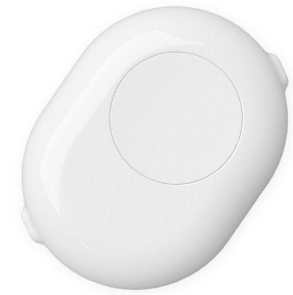
Shelly Button Add-on is an accessory that allows Shelly smart switches or dimmers to be used safely without inserting them into the wall box. It can be used with a wide range of plus and mini form-factor devices and easily turns every night light, fan or convector into a smart device.
Compatibility
-
Gen1 devices: Shelly 1/1PM, Shelly 2.5 (switch mode), Shelly Dimmer 2
-
Gen2 devices: Shelly Plus 1/1PM, Shelly Plus 2PM (switch mode), Shelly Plus 1/1PM Mini
-
Gen3 devices: Shelly 1/1PM Gen3, Shelly 2PM Gen3 (switch mode), Shelly 1/1PM Mini Gen3, Shelly Dimmer Gen3 (when used with neutral)
-
Gen4 devices (available so far): Shelly 1/1PM Gen4, Shelly 1/1PM Mini Gen4
Main features
-
Retrofit: turn every night-light, ambient light, fan or other appliance into a smart device
-
Ease of access: provide easy and safe access for children and people with disabilities to the home lights, fans or other devices
-
Mounting: fast and easy wiring by using the pre-installed cables
-
Compatibility: can be used with wide range of plus and mini form-factor Shelly devices
Use cases
-
Retrofitting: Turn your night lights into smart lights without the need of additional wiring, just insert a Shelly device of your choice and replace the existing switch with this elegant accessory.
-
Comfort for children: Install it near your child’s bed and let the kid turn on and off the lights whenever they want. Dim down the lights remotely to provide comfortable environment without entering the room.
-
Ease of access: Use it as additional wall switch for the lights to provide easy access for disabled people without the need of any construction works.
Main applications
-
Residential
-
MDU (Multi Dwelling Units - apartments, condominiums, hotels, etc.)
-
Light commercial (small office buildings, small retail/restaurant/gas station, etc.)
-
Government/municipal
-
University/college
Device electrical interfaces
Inputs:
-
2 power supply inputs on push-in terminals: N (+) and L (Ʇ)
Outputs:
-
2 power supply outputs on push-in terminals: N (+) and L (Ʇ)
Interconnections:
-
5 cables: 1 L and 1 I (brown), 1 N (blue), 1 O (black) and 1 SW (white)
Supported load types
Load type should be compatible with the Shelly device that is going to be used with Shelly Button Add-on.
Specifications
| Quantity | Value |
|---|---|
| Physical | |
| Size (HxWxD): | 63x84x28 mm |
| Weight: | 45.62 g |
| Terminals: | Push-in |
| Power cable (size) | 3 mm |
| Conductor cross section: | 0.2 to 1.5 mm² /24 to 16 AWG (solid, stranded, and bootlace ferrules) |
| Conductor stripped length: | 7 to 8 mm |
| Mounting: | Stand-alone/surface mounting |
| Shell material: | Plastic |
| Shell and print colors: | White shell, matte, gray print Black shell, matte, white print |
| Connectors color: | Black |
| Cables colors | Brown, Blue, Black, White |
| Cables length | 35 mm |
| Environmental | |
| Ambient working temperature: | -20°C to 40°C |
| Humidity: | 30% to 70% RH |
| Max. altitude: | 2000 m |
| Electrical | |
| Power supply: | 220-240 V~ 50 Hz |
| Output circuits ratings | |
| Max. switching voltage: | 240 V~ |
| Max. switching current: | 3 A and less than the rating of the Shelly device that is used. |
Basic wiring diagrams
_wiring%20diagram.png?cb=0a74344a9fc54051466ed48f54b53d64)
_wiring%20diagram-20250613-151152.png?cb=28d3972d1cc1896043bb187894a4497e)
_wiring%20diagram.png?cb=b577e143c33a2479147795fcfd5bdaa0)
_wiring%20diagram-20250613-151102.png?cb=23d0373dfa6a84733c2b75a75fb7616d)
_wiring%20diagram-20250613-151023.png?cb=fe45db52fff4b5862ed64fc97944f3bb)
_wiring%20diagram.png?cb=d8c2746c6057e62940324acbb1bd520e)
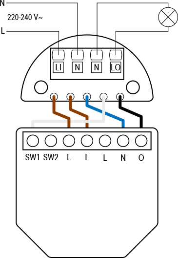
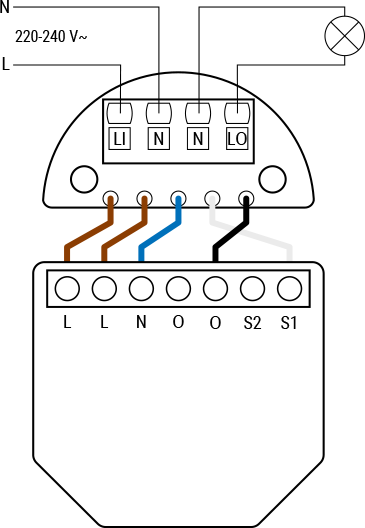
Legend
| Terminals | Wires | ||
|---|---|---|---|
| Push-in terminal block | Wires | ||
| LI: | Live In (incoming live wire from power source) | N: | Neutral wire |
| N: | Neutral terminals (x2) | L: | Live wire (220-240 V~) |
| LO: | Live Out (switched live wire going to the output) | Brown: | Wire for live/input terminal |
| Device terminals | Blue: | Wire for neutral terminal | |
| L: | Live terminal (220-240 V~) | White: | Wire for switch terminal |
| N: | Neutral terminal | Black: | Wire for output terminal |
| O, O1, O2: | Load circuit output terminals | | |
| I: | Load circuit input terminal | | |
| S1, S2, SW, SW1, SW2: | Switch input terminals | | |