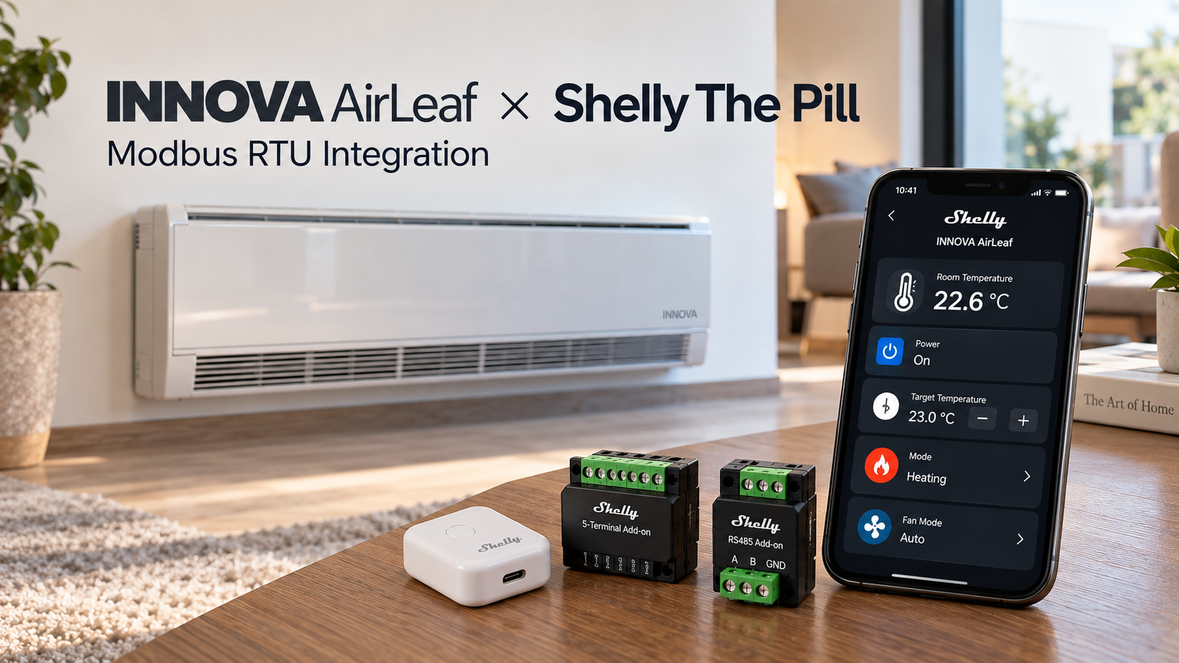
Control and monitor compatible INNOVA AirLeaf fan coil units directly through Shelly Smart Control using Shelly The Pill and the Modbus RS485 Add-on.
This integration provides local Modbus communication, temperature monitoring, operating mode selection, fan control, alarm diagnostics, and remote access through Shelly Smart Control — without requiring Home Assistant, Node-RED, an external Modbus gateway, or a separate automation server.
Three board-specific INNOVA profiles are available. The contributor reported successful hardware testing of earlier Modbus integrations; the updated firmware-managed Virtual Component lifecycle and selectable Modbus Slave ID still require verification on the target Shelly firmware and real controllers.
Overview
Modern fan coil installations often require centralized control, remote monitoring, and integration with building automation systems.
INNOVA AirLeaf fan coil units equipped with compatible Modbus RTU controllers can be integrated directly into the Shelly ecosystem.
This solution uses:
-
Shelly The Pill
-
Shelly Modbus RS485 Add-on
-
A compatible INNOVA AirLeaf controller
-
Shelly Script
-
Shelly firmware-managed Virtual Components
-
Shelly Smart Control
The Shelly device communicates with the INNOVA controller over a local RS485 connection.
A dedicated Shelly Script reads the relevant Modbus registers and synchronizes values with nine firmware-managed Virtual Components. One of them, Modbus Slave ID, lets the installer choose the remote controller address directly in the Shelly interface without editing the script.
Where supported and explicitly enabled, these components can also issue control commands to the fan coil.
The result is a compact and flexible integration suitable for residential and commercial HVAC applications.
How the integration works
The architecture uses a direct local communication path:
INNOVA AirLeaf / compatible controller Modbus RTU slave address: 1–247 │ RS485 (A/B) │ Shelly RS485 Add-on │ Shelly The Pill ┌──────┴──────┐ │ │ Modbus RTU Client Shelly Script │ │ └──────┬──────┘ │ 9 managed Virtual Components ├─ Power, temperatures, modes ├─ Fan control and diagnostics └─ Modbus Slave ID (saved setting) │ Local Wi-Fi │ Shelly Smart Control Monitoring / Control Modbus communication and script execution are performed locally.
Shelly Cloud provides remote access and visualization but is not required for the local Modbus polling logic.
Communication sequence
At startup, the Shelly firmware creates or reconciles the nine managed Virtual Components declared in the script's first-line @meta metadata. The script then:
-
Resolves each component through
Script.getVcHandle(role)rather than relying on fixed numeric component IDs. -
Reads the persisted Modbus Slave ID setting (integer 1–247, default 1 on a new installation).
-
Checks that the local Serial interface is already configured as Modbus client, 9600 baud, 8N1. It does not change serial settings automatically.
-
Starts polling the selected INNOVA slave's documented Holding Registers using Modbus FC03.
-
Converts register values into temperature, operating-mode, fan-mode, and alarm information.
-
Updates the corresponding Virtual Components.
-
Accepts supported control requests only after
ENABLE_WRITES=trueand a fresh read of the required controller state. -
Issues confirmed, guarded writes with FC06, then polls the controller again to display its reported values.
Changing Modbus Slave ID: the script switches the address used for outgoing requests, clears cached state, rejects replies belonging to the previous address, and requires fresh readings before accepting new commands. This does not change the physical Modbus address configured inside the INNOVA controller. Already-transmitted commands cannot be cancelled.
This approach keeps the Shelly interface aligned with the controller's reported state without relying on an external automation server.
Supported INNOVA controllers
Three dedicated scripts are available.
| INNOVA controller | Control board | Integration |
|---|---|---|
| ECA644 | INN-FR-B32 | Supported profile |
| ECA647 | INN-FR-B32 | Supported profile |
| EDA649 | ESE645 | Supported profile |
| EDB649 | ESE645 | Supported profile |
| Compatible configurations using ESE648 | ESE648 | Supported profile |
These profiles are based on the INNOVA Modbus documentation N273025C.
Contributor-reported physical tests of the INNOVA Modbus integrations predate the latest managed-component and live slave-selection changes. The revised scripts must undergo fresh hardware testing before being considered validated for deployment.
Important: Compatibility depends on the installed control electronics, not only on the fan coil model designation.
Other INNOVA controllers, including EWF644II, are not covered by this Modbus register mapping without additional verification.
INNOVA EWF644II with a suitable Wi-Fi controller may require a separate HTTP-based integration; these three Modbus RTU scripts are not interchangeable with that solution.
Requirements
Hardware
| Component | Purpose |
|---|---|
| Shelly The Pill | Local controller and Wi-Fi connectivity |
| Shelly Modbus RS485 Add-on | Physical RS485 interface |
| Required Shelly add-on interface and power supply | Connection and power for the add-on assembly |
| INNOVA AirLeaf | Fan coil with compatible Modbus controller |
| RS485 twisted-pair cable | Communication between devices |
The integration does not require a separate RS485-to-Ethernet converter.
Software
The Shelly firmware must support:
-
Shelly Script execution
-
Modbus RTU Client
-
Serial component
-
Managed Virtual Components (
@metaandScript.getVcHandle()) -
Shelly Smart Control connectivity
The @meta declaration must appear on the first physical line of each script, and its length must remain within the firmware metadata limit (1024 characters in the current implementation). The firmware owns the virtual-component lifecycle; the script binds the handles by role, with no Virtual.Add calls.
Use firmware confirmed to support managed script components. The new startup and component lifecycle require a real-device smoke test; a previously reported restart problem on The Pill Gen3 firmware 2.0.1-ge1a198b may affect managed-component scripts.
RS485 wiring
The INNOVA controller and Shelly RS485 Add-on must be connected through their respective RS485 terminals.
Basic connection:
INNOVA AirLeaf Shelly RS485 Add-on RS485 A ─────────────────────── A RS485 B ─────────────────────── B Verify the terminal markings in the documentation for the specific INNOVA control board.
The terminal names may differ between control boards.
Where required by the hardware documentation, connect the communication reference according to the manufacturer's instructions.
Wiring recommendations
Use twisted-pair cable suitable for RS485 communication.
Keep the communication cable away from high-current electrical wiring where practical.
Avoid star topology and use appropriate termination at the ends of the bus.
If communication cannot be established, verify the A/B polarity, Modbus slave address, serial configuration, and wiring.
Never connect mains voltage to the RS485 communication terminals.
Modbus RTU configuration
The provided scripts expect the following configuration:
| Parameter | Value |
|---|---|
| Protocol | Modbus RTU |
| Interface | RS485 |
| Baud rate | 9600 |
| Data bits | 8 |
| Parity | None |
| Stop bits | 1 |
| Serial format | 8N1 |
| Modbus reading | FC03 — Read Holding Registers |
| Modbus writing | FC06 — Write Single Register, when enabled |
| Shelly Modbus Client ID |
|
| Remote slave address | Selected through the Modbus Slave ID Virtual Component, |
| Default remote slave address |
|
| Polling timer | 3500 ms; one register is read per polling step |
The Modbus Slave ID field in Shelly must match the address already configured on the physical INNOVA controller. Setting this field selects where Shelly sends requests; it does not reprogram the controller.
The scripts check the serial configuration before beginning communication.
They do not automatically change the device's serial settings.
Script configuration
The scripts currently contain these operational settings:
var SLAVE_ID = 1; // Runtime value is loaded from the managed Modbus Slave ID VC var CLIENT_ID = 0; var ENABLE_WRITES = false; var POLL_MS = 3500; var EXPECTED_BAUD = 9600; Do not edit SLAVE_ID to change the remote device address. It is initialized from the persisted Modbus Slave ID Virtual Component (role: slaveId) when the script starts. Use the Number field in the Shelly interface instead.
-
CLIENT_IDidentifies the local Shelly Modbus RTU Client instance. -
POLL_MSis the timer period between individual register-reading attempts. The B32 profile polls 7 registers (approximately 24.5 seconds per full cycle); ESE645/ESE648 poll 6 registers (approximately 21 seconds per cycle). -
EXPECTED_BAUDis used to check the existing serial configuration. -
ENABLE_WRITESenables or blocks commands from Power, Target Temperature, Operating Mode, and Fan Mode; it isfalseby default.
For initial commissioning, keep:
var ENABLE_WRITES = false; This is read-only mode: the script still reads registers and updates virtual components, but it does not send fan-coil control commands.
Only after confirming the exact controller, register scaling, physical behavior, and safety requirements should write access be enabled by changing the code to:
var ENABLE_WRITES = true; A write response from Modbus alone does not prove that the equipment acted; check fresh readback and physical operation.
Modbus register mapping
The integrations use a selection of registers from the INNOVA N273025C documentation.
The following table covers the primary registers used by the scripts.
| Register | Parameter | Description |
|---|---|---|
| 0 | Room Temperature | Current room temperature |
| 1 | Hot Water Temperature | Water temperature on compatible B32 boards |
| 8 | Actual Setpoint | Actual controller setpoint |
| 15 | Motor Speed Command | Commanded motor-speed value on B32 |
| 105 | Alarm Status | Controller alarm flags |
| 201 | PRG | Standby and fan program |
| 231 | Setpoint | Requested temperature |
| 233 | Operating Mode | Heating/cooling selection |
Temperatures use a scaling factor of 0.1°C where specified.
For example:
Modbus register value: 225 Temperature: 22.5°C The scripts use zero-based Modbus register addresses.
Power control
Register 201 contains the program and standby configuration.
The standby flag is represented by bit 7.
The script modifies this bit while preserving the unrelated bits.
Fan operating mode
The fan program is also controlled through register 201.
The implemented options are:
| Value | Fan program |
|---|---|
| 0 | Auto |
| 1 | Silent |
| 2 | Night |
| 3 | Maximum |
These are operating programs, not direct motor RPM commands.
Heating and cooling
Register 233 contains the operating mode selection.
| Value | Mode |
|---|---|
| 0 | Auto |
| 3 | Heating |
| 5 | Cooling |
The script exposes the controller's reported mode. Automatic-mode write selection is not included in the current command handler.
Shelly Managed Virtual Components
Each INNOVA script declares exactly nine firmware-managed Virtual Components, created from its first-line @meta metadata and resolved by Script.getVcHandle(role). They do not use fixed virtual-component IDs. No Group component is added.
| # | Virtual Component name | Type | Role / function |
|---|---|---|---|
| 1 | INNOVA Power | Boolean | Controller on/standby state (register 201, bit 7) |
| 2 | Room temperature | Number | Room temperature (register 0, scaled by 0.1°C) |
| 3 | Target temperature | Number | Requested setpoint (register 231, scaled by 0.1°C) |
| 4 | Operating mode | Enum |
|
| 5 | Fan mode | Enum |
|
| 6 | Water temperature or Actual setpoint | Number | Board-specific measurement (register 1 or 8) |
| 7 | Motor speed command or Raw program flags | Number | Board-specific diagnostic data (register 15 or 201) |
| 8 | Modbus diagnostics | Text | Alarm flags (register 105) and communication diagnostics |
| 9 | Modbus Slave ID | Number | Editable, persisted remote Modbus address (1–247) |
The first eight components retain their existing roles. The previous Modbus online Boolean component has been removed to make room for the configurable slave address. Communication state is still tracked internally, and errors are reported through Modbus diagnostics and script logs.
A device must have enough available managed-VC capacity (nine slots). Do not run multiple INNOVA profiles on the same Shelly host.
B32 profile
For supported INN-FR-B32 controllers:
Component 6 — Water temperature
Reads water temperature from register 1 (0.1°C scaling).
Component 7 — Motor speed command
Reports register 15. This is a commanded motor-speed value, not independently measured fan RPM.
ESE645 and ESE648 profiles
For these two controller profiles:
Component 6 — Actual setpoint
Reports the controller's actual setpoint from register 8 (0.1°C scaling).
Component 7 — Raw program flags
Reports the raw program word from register 201, rather than a measured motor speed.
These profiles do not advertise the B32-only water sensor or motor register as available measurements.
Choosing the Modbus address from Shelly
Component 9 — Modbus Slave ID is a managed Number field with:
| Setting | Value |
|---|---|
| Type |
|
| Managed role |
|
| Minimum |
|
| Maximum |
|
| Step |
|
| Initial value |
|
| Persistence |
|
| UI presentation | Editable numeric field |
For example, if the physical INNOVA controller is already configured with Modbus slave address 12, set Modbus Slave ID = 12 in Shelly. The script will send the following requests to slave 12 without changing the JavaScript.
When the address is changed, the script clears data cached from the previously selected controller, rejects stale read and write callbacks, and waits for fresh readings. Commands remain blocked until the new target's required registers have been read. The selected address is retained after Shelly restarts.
This does not modify the controller's own slave address. The address must be configured on the INNOVA unit according to its documentation, then selected in Shelly.
Invalid selections, including non-integers or values outside 1–247, are rejected, with the previous valid address restored.
Communication diagnostics
Modbus diagnostics reports conditions such as:
-
Waiting for the selected Modbus slave.
-
Serial configuration mismatch.
-
Modbus communication error for the selected slave.
-
Alarm flags returned from register 105.
-
Failed write attempts, when writes are enabled.
There is no standalone Modbus Online switch in the current scripts. The internal online state is used as a command-safety guard.
Installing the Shelly Script
The latest three managed-VC scripts are available in the open upstream contribution:
https://github.com/ALLTERCO/shelly-script-examples
These URLs reference the updated source branch, not potentially outdated copies in an older standalone repository. The PR is under review, and its changes are not yet necessarily available in the upstream main branch.
Select the appropriate script
INN-FR-B32 — ECA644 / ECA647
https://github.com/ALLTERCO/shelly-script-examples/blob/main/modbus/innova-airleaf-b32.shelly.js
ESE645 — EDA649 / EDB649
https://github.com/ALLTERCO/shelly-script-examples/blob/main/modbus/innova-airleaf-ese645.shelly.js
ESE648 — verified compatible configurations
https://github.com/ALLTERCO/shelly-script-examples/blob/main/modbus/innova-airleaf-ese648.shelly.js
Choose the script based on the actual control board, not just the fan-coil product name. Install only one profile per Shelly host.
Installation steps
-
Identify the fan-coil controller board and its current Modbus address.
-
Connect Shelly The Pill and the appropriate RS485 Add-on following both hardware manuals.
-
Open the Shelly device's local web interface.
-
Set the Serial component to Modbus RTU Client (
mb_client), 9600 baud, 8N1. The scripts only check these settings; they do not configure Serial automatically. -
Back up existing scripts, scenes, and Virtual Components. If migrating from a version that used
Virtual.Add, stop the old script and remove only verified obsolete INNOVA VCs; otherwise there may not be enough slots. -
Open Scripts, create a new script, and paste the complete
.shelly.jsfile for the correct profile. Keep its first-line@metadeclaration intact. -
Leave
ENABLE_WRITES=false, save the script, and start it. Firmware creates the nine managed components and assigns their numeric IDs. -
Open the new Modbus Slave ID Virtual Component and enter the actual controller address (a whole number from 1 through 247). The value is saved for subsequent restarts.
-
Check the script logs and compare the reported temperatures, target, operating mode, and alarms with the original INNOVA controller.
-
After completing register-map and safety verification, enable the four available control commands only if the installation permits them.
Managed Virtual Components are owned by the firmware; stopping and deleting the owning script may affect their lifecycle. Do not assume that old manually created component IDs will remain valid.
First startup
With the supported firmware and sufficient VC capacity, the startup path is:
Firmware reads first-line @meta │ ▼ Creates/reconciles nine managed VCs │ ▼ Script resolves handles by role │ ▼ Loads saved Modbus Slave ID (1–247) │ ▼ Checks Serial = mb_client 9600 / 8N1 │ ▼ Starts periodic FC03 reads │ ▼ Updates temperature, modes, fan data and diagnostics VCs │ ▼ Shelly interface For a newly installed script with the default address, the expected startup log includes:
[INNOVA b32] Started READ-ONLY=true, slave=1 The profile name and address change according to the selected script and persisted setting. For a controller on address 12, the corresponding log ends with slave=12.
Checking communication
Open the script logs to verify that the script starts polling. If its serial configuration is incorrect, it deliberately refuses to poll and reports Serial configuration mismatch in Modbus diagnostics.
If the remote controller does not reply, the script reports a Modbus communication error after repeated failures. It does not expose a separate Modbus online VC.
For additional diagnostics, the local RPC endpoints include:
-
http:///rpc/Serial.GetConfig?id=0 -
http:///rpc/Shelly.GetComponents?dynamic_only=true -
http:///rpc/Script.GetStatus?id=
Use the actual script ID for the last URL. Managed VC numeric IDs are assigned by the firmware; do not hard-code them in other scripts or scenes.
Enabling control
After verifying the reported values and the correct register mapping, the supported commands can be enabled.
Change:
var ENABLE_WRITES = false; to:
var ENABLE_WRITES = true; Save and restart the script.
The following user-facing control operations are implemented:
| Function | Modbus register |
|---|---|
| Power / Standby | 201 |
| Target Temperature | 231 |
| Heating / Cooling | 233 |
| Fan Program | 201 |
The target-temperature command accepts values from 16°C to 30°C in increments of 0.1°C.
Command synchronization
When a control value is changed:
Shelly Smart Control │ ▼ Virtual Component │ ▼ Shelly Script │ ▼ Modbus Write – FC06 │ ▼ INNOVA AirLeaf │ ▼ Subsequent Modbus Read │ ▼ Virtual Component Update The integration uses subsequent polling to synchronize the interface with the controller.
The local INNOVA control logic remains responsible for the fan coil's operation and protections. Address selection in Shelly does not configure the INNOVA hardware.
Troubleshooting
No Modbus communication
Check the following:
-
RS485 A/B wiring and polarity.
-
Correct value in the Modbus Slave ID Virtual Component (1–247), matching the actual INNOVA controller address.
-
Matching serial settings (mb_client, 9600, 8N1).
-
Modbus RTU Client mode.
-
Compatible INNOVA controller.
-
RS485 termination and physical wiring.
Virtual Components are missing
Verify that the installed firmware supports managed Virtual Components.
Confirm that another script is not using the available component resources.
Check the script logs for initialization errors.
Each variant declares nine managed Virtual Components, but their successful creation and presentation depend on the installed Shelly firmware and device resources.
Values are not updating
Check the Modbus diagnostics text component and the script logs for communication errors.
Compare the register values against the physical INNOVA controller.
Verify that the selected script corresponds to the installed control board.
Commands do not change the fan coil state
Confirm that:
var ENABLE_WRITES = true; Verify that the requested operation is permitted by the INNOVA controller configuration.
The controller may apply additional operating restrictions, setpoint limits, or safety conditions.
Safety and limitations
The integration is intended to extend the monitoring and control capabilities of compatible INNOVA AirLeaf systems.
It does not replace the original INNOVA control electronics or their safety functions.
The Shelly Script should not be used as the primary safety interlock, freeze-protection mechanism, or thermal-protection system.
Before enabling control commands, verify the controller model, register map, operating limits, and electrical installation.
The published scripts are configured for read-only operation by default.
The contributor reported earlier successful hardware testing for INNOVA Modbus integration. The new managed-VC lifecycle and user-editable slave selection have not yet been independently validated on all target hardware/firmware combinations. Passing automated checks does not replace a physical commissioning test.
Practical applications
The solution can be used in a variety of HVAC installations, including:
Residential buildings
Monitor and control fan coil operation through Shelly Smart Control.
Office buildings
Provide local fan coil monitoring and basic control without a dedicated BMS server.
Hotels and hospitality
Integrate compatible fan coil units into room automation systems.
Schools and educational buildings
Monitor room temperatures, setpoints, operating modes, and Modbus diagnostic messages.
Commercial HVAC systems
Combine compatible fan coil installations with other Shelly devices and automation logic.
Result
The integration demonstrates how Shelly The Pill can serve as a compact Modbus RTU client for compatible INNOVA AirLeaf systems. The current managed-component revision is available for review and requires firmware-specific hardware validation before production use.
Through a direct RS485 connection, selected HVAC operating values can be monitored and supported commands can be issued through Shelly Virtual Components.
The solution offers:
-
Local Modbus RTU communication.
-
Integration with Shelly Smart Control.
-
Nine firmware-managed Virtual Components per controller profile.
-
Heating and cooling mode selection.
-
Fan operating program control.
-
Temperature monitoring and setpoint adjustment.
-
Alarm and communication diagnostics.
-
Persisted Modbus Slave ID selection (1–247) directly in Shelly.
-
No requirement for an external automation server.
Three controller-specific implementations are available, making the approach adaptable to different INNOVA AirLeaf installations.
Resources
Current source and upstream contribution
INNOVA scripts — Pull Request #228
Register documentation
Shelly APIs
Modbus RTU Client · Managed Virtual Components · Serial
We Value Your Feedback!
Thank you for taking the time to read our article! Was it helpful or interesting?
Your insights can help us improve. We’d be grateful for any feedback. If you have a moment,
please share it with us at the following email:


