


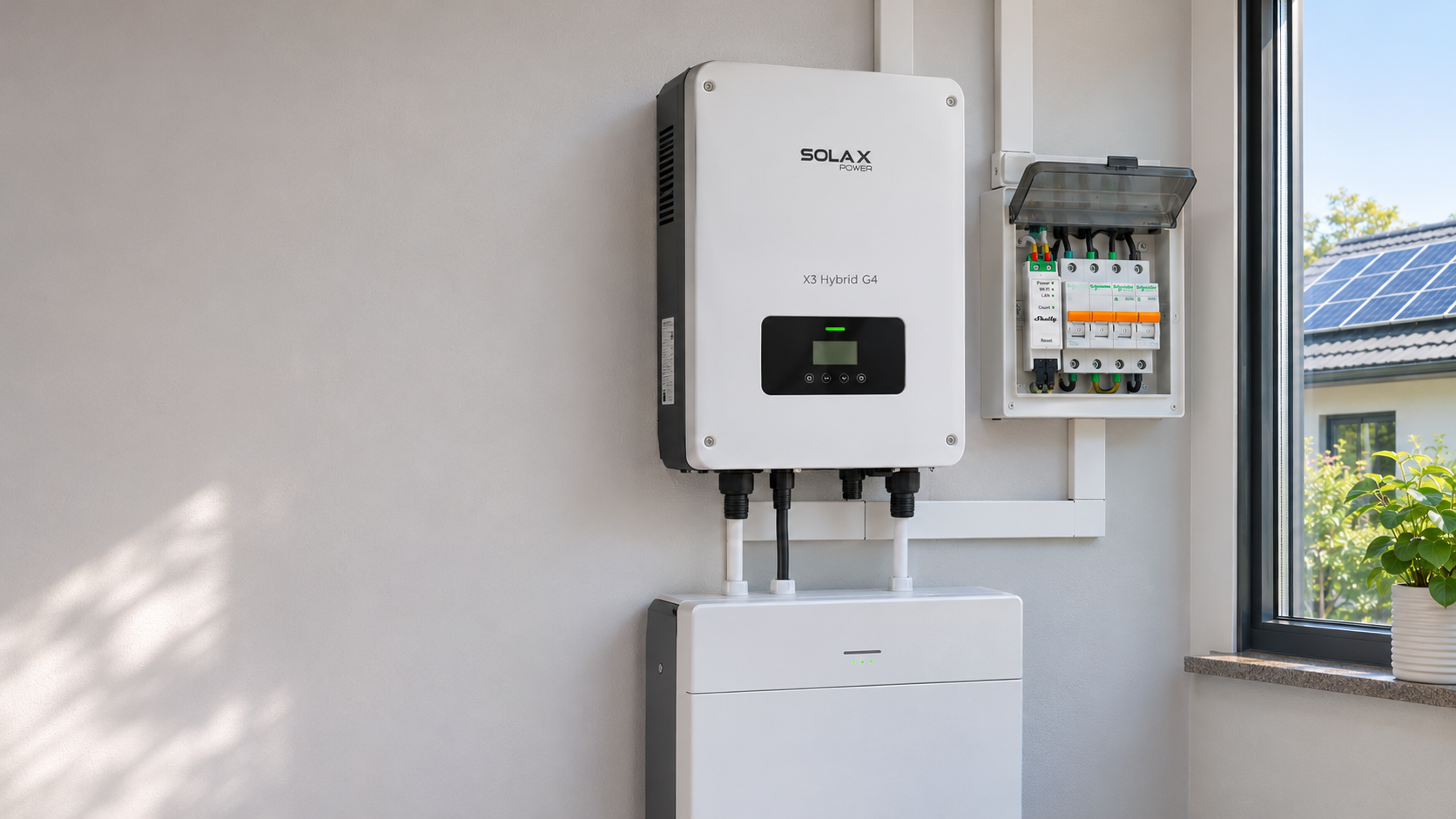
Integrate the SolaX X3 Hybrid G4 inverter with Shelly using local HTTP communication. Monitor solar production, household consumption, grid power, and battery status directly in Shelly Smart Control without additional servers or cloud APIs.
This integration enables real-time monitoring of photovoltaic generation, household electricity consumption, grid import and export, battery charging and discharging, and inverter operating conditions.
The solution uses Shelly Script and Virtual Components to retrieve and display inverter data directly over the local network, without requiring the SolaX Cloud API, Home Assistant, Node-RED, or an additional communication gateway.
Overview
The Shelly device communicates with the SolaX inverter through its local communication dongle.
A dedicated Shelly Script periodically sends HTTP requests, processes the received data, and publishes the measurements as Virtual Components accessible through the Shelly device's local web interface and Shelly Smart Control.
The integration provides the following measurements:
-
PV Power: Instantaneous power generated by the photovoltaic panels.
-
Grid Power: Power exchanged with the electrical grid.
-
Load Power: Current household or building electricity consumption.
-
Battery Power: Battery charging or discharging power.
-
Battery SoC: Battery State of Charge, expressed as a percentage.
-
Total Energy: Total electrical energy generated by the inverter.
-
Heatsink Temperature: Temperature of the inverter's heatsink.
-
Operating Mode: Current operating state of the inverter.
An additional Virtual Component, Dongle SN, allows the communication dongle's serial number to be configured directly through the Shelly interface.
Compatibility: The script is designed for the SolaX X3 Hybrid G4 response structure identified as type 14. Compatibility with other inverter models, communication dongles, and firmware versions should be verified before installation.
How the Integration Works
The Shelly device acts as an HTTP client, periodically requesting operational data from the SolaX communication dongle.
During each polling cycle, the script performs the following operations:
-
Reads the serial number stored in the
Dongle SNVirtual Component. -
Sends an HTTP POST request to the configured local IP address of the communication dongle.
-
Receives a JSON response containing the inverter's operational data.
-
Validates the response and extracts the required measurements from the
Dataarray. -
Converts the raw values into their corresponding engineering units.
-
Updates the Shelly Virtual Components.
The default polling interval is 15 seconds.
The script also performs an immediate request when it starts and whenever the communication dongle's serial number is changed.
This allows the measurements to remain regularly updated without requiring manual intervention.
Local Communication and Remote Monitoring
Communication between the Shelly device and the SolaX inverter takes place entirely over the local IP network.
The script does not depend on the SolaX Cloud infrastructure to retrieve measurements.
Once the Shelly device is connected to Shelly Smart Control, the data can also be viewed remotely using Shelly's standard cloud connectivity.
This approach makes it possible to monitor inverter measurements alongside other Shelly devices within the same smart home or building automation environment.
The local HTTP communication continues to operate independently of the SolaX cloud service.
Requirements
The following equipment is required to implement the integration:
| Equipment | Purpose |
|---|---|
| SolaX X3 Hybrid G4 | Hybrid photovoltaic inverter |
| Compatible SolaX communication dongle | Provides the local HTTP interface |
| Shelly device with scripting support | Executes the integration script |
| Local IP network | Enables communication between Shelly and SolaX |
| Shelly Smart Control | Monitoring and visualization |
The Shelly device must support managed Virtual Components and the required Shelly Script API functions.
The group membership declaration used by this script requires compatible firmware 2.2.0 or later, with support for the necessary managed-component features.
The integration creates a total of 10 Virtual Components:
-
7 numerical components.
-
2 text components.
-
1 group.
On Shelly devices with a limit of 10 Virtual Components, the integration uses the entire available capacity.
No dedicated relay output, Shelly Modbus Add-on, RS485 connection, or direct wiring to the inverter's communication terminals is required.
Any compatible Shelly device with sufficient scripting resources and reliable local network connectivity can serve as the integration host.
Network Configuration
Before installing the script, verify the following:
-
The SolaX communication dongle is connected to the local network.
-
The dongle has a valid IPv4 address.
-
The communication dongle's serial number is available.
-
The Shelly device can reach the dongle over TCP port 80.
-
The selected Shelly device supports Scripts and managed Virtual Components.
-
Sufficient Virtual Component capacity is available.
It is recommended to configure a DHCP reservation for the SolaX communication dongle.
This ensures that its IP address remains unchanged after a router or dongle restart.
If Shelly and SolaX are connected to different VLANs or network segments, the appropriate routing and firewall rules must allow communication between them.
The devices do not necessarily need to use the same Wi-Fi network, provided that they can communicate over IP.
Local HTTP Communication
The integration uses the communication dongle's local HTTP interface to retrieve operational data from the inverter.
Communication Parameters
| Parameter | Value |
|---|---|
| Protocol | HTTP |
| Method | POST |
| Destination |
|
| Content-Type |
|
| Operation |
|
| Authentication field | Communication dongle serial number |
| Polling interval | 15 seconds |
| Request timeout | 10 seconds |
HTTP Request
The Shelly device sends an HTTP POST request with the following body:
optType=ReadRealTimeData&pwd=YOUR_DONGLE_SN For example, if the communication dongle has the IP address 192.168.1.50, the request is sent to:
http://192.168.1.50/ The pwd parameter contains the communication dongle's serial number.
The serial number is configured through the Dongle SN Virtual Component.
Do not use the SolaX Cloud account password or assume that the inverter's serial number is interchangeable with the communication dongle's serial number.
The request is sent directly to the root path / of the dongle's local HTTP server.
HTTP Response Structure
The communication dongle returns a JSON response containing the inverter's current operational data.
A simplified example of the response structure is shown below:
{ "sn": "REDACTED", "ver": "EXAMPLE_VERSION", "type": 14, "Data": [], "Information": [] } The example illustrates the response structure only. A valid operational response contains numerical measurements in the Data array.
The script retrieves the required measurements from predefined array positions according to the SolaX type 14 data layout.
Unlike a JSON API that provides descriptive fields such as pv_power or battery_soc, this interface stores measurements at specific numerical indexes.
The script verifies that the Data array contains at least 110 elements before processing the measurements.
Shelly Script Configuration
The integration script is available in the official ALLTERCO GitHub repository.
Download SolaX X3 Hybrid G4 Local HTTP Shelly Script
The main configuration is located near the beginning of the script:
let CFG = { ip: "192.0.2.10", period: 15000, // Timer.set() uses milliseconds. }; IP Address Configuration
Replace the default IP address with the actual local address of the SolaX communication dongle.
For example:
let CFG = { ip: "192.168.1.50", period: 15000, }; Enter only the IP address in CFG.ip.
The script automatically adds the http:// prefix and trailing slash when constructing the request URL.
Polling Interval
The period parameter determines the interval between HTTP requests.
The value is expressed in milliseconds.
15000 ms = 15 seconds The default interval is recommended for initial commissioning.
The communication dongle's serial number is configured separately through the Dongle SN Virtual Component.
Inverter Data Mapping
The script extracts and processes measurements from the JSON response's Data array.
The indexes listed below are zero-based array positions, not Modbus register addresses.
Measurement Mapping
| Measurement | Data Index | Processing | Unit |
|---|---|---|---|
| PV Power | 14 and 15 | Sum of PV1 and PV2 power | W |
| Grid Power | 34 and 35 | Signed 32-bit value | W |
| Load Power | 47 | Signed 16-bit value | W |
| Battery Power | 41 | Signed 16-bit value | W |
| Battery SoC | 103 | Direct value | % |
| Total Energy | 68 and 69 | Signed 32-bit value divided by 10 | kWh |
| Heatsink Temperature | 54 | Signed 16-bit value | °C |
| Operating Mode | 19 | Numeric status code converted to text | Text |
Some measurements are represented as signed integers and require conversion before being displayed.
Signed 16-bit Values
Signed 16-bit values can represent both positive and negative numbers.
Raw values below 32768 are interpreted as positive.
Values from 32768 to 65535 are converted by subtracting 65536.
For example:
| Raw Value | Converted Value |
|---|---|
| 1200 | 1200 |
| 0 | 0 |
| 64336 | -1200 |
This conversion allows the script to correctly represent electrical power flowing in different directions.
Signed 32-bit Values
Certain measurements are stored across two consecutive 16-bit words.
The script combines the lower and higher words using the following calculation:
unsigned_32 = low_word + high_word * 65536 The resulting value is then converted into a signed 32-bit integer when necessary.
For the Total Energy measurement, an additional scaling factor is applied.
For example:
Raw value = 123456 Total Energy = 123456 / 10 Total Energy = 12345.6 kWh This produces the inverter's cumulative energy reading in kilowatt-hours.
Power Flow Direction
The integration uses the following sign conventions:
| Measurement | Value | Interpretation |
|---|---|---|
| Grid Power | Positive | Importing electricity from the grid |
| Grid Power | Negative | Exporting electricity to the grid |
| Battery Power | Positive | Battery charging |
| Battery Power | Negative | Battery discharging |
These conventions are important when configuring energy monitoring dashboards and visual representations of electrical power flows.
The direction of power flow should be verified against the original SolaX monitoring interface during commissioning.
Example of an Energy Balance
Consider the following measurements:
| Measurement | Value |
|---|---|
| PV Power | 4820 W |
| Load Power | 2900 W |
| Grid Power | -720 W |
| Battery Power | 1200 W |
The readings indicate that:
-
The photovoltaic system is generating 4820 W.
-
The building is consuming 2900 W.
-
The battery is charging at 1200 W.
-
Approximately 720 W is being exported to the electrical grid.
The simplified energy balance is:
PV = Load + Battery Charging + Grid Export 4820 W = 2900 W + 1200 W + 720 W This provides a convenient way to verify that the measurements are consistent with the expected operation of the photovoltaic system.
Small differences may occur in real installations because of inverter conversion losses, measurement tolerances, and differences in sampling times.
Shelly Virtual Components
The script automatically creates the necessary Virtual Components through the @meta declaration at the beginning of the source file.
All components are organized under a single group:
Solax X3 Hybrid G4
Virtual Component Overview
| Component | Type | Unit | Description |
|---|---|---|---|
| PV Power | Number | W | Photovoltaic generation |
| Grid Power | Number | W | Grid import or export |
| Load Power | Number | W | Household electricity consumption |
| Battery Power | Number | W | Battery charging or discharging |
| Battery SoC | Number | % | Battery State of Charge |
| Total Energy | Number | kWh | Total generated energy |
| Heatsink Temperature | Number | °C | Inverter heatsink temperature |
| Operating Mode | Text | | Inverter operating state and communication status |
| Dongle SN | Text | | Communication dongle serial number |
The Dongle SN component is editable and stores the communication dongle's serial number.
When its value changes, the script automatically initiates a new HTTP request.
The generated group provides a convenient way to monitor all inverter measurements from a single location.
The Virtual Component IDs are assigned automatically by the Shelly firmware.
The script identifies its managed components by their declared roles rather than relying on fixed numerical component IDs.
Virtual Components in the Shelly Interface
The numerical components display the measurements using their corresponding engineering units.
For example:
-
PV Power is displayed in watts.
-
Battery SoC is displayed as a percentage.
-
Total Energy is displayed in kilowatt-hours.
-
Heatsink Temperature is displayed in degrees Celsius.
The values can be accessed through the Shelly device's local interface and supported Shelly Smart Control features.
Figure 1. SolaX Virtual Components in Shelly
Figure 1. SolaX X3 Hybrid G4 measurements displayed as Shelly Virtual Components. The communication dongle's serial number has been hidden.
Installing the Integration
The installation process is performed entirely through the Shelly device's local web interface.
Creating the Script
-
Open the local web interface of the selected Shelly device.
-
Navigate to the
Scriptssection. -
Create a new script named
SolaX X3 Hybrid G4. -
Open the official GitHub source file.
-
Select
Rawand copy the complete source code. -
Paste the code into the Shelly Script editor.
-
Keep the original
@metadeclaration unchanged. -
Configure
CFG.ipwith the communication dongle's local IP address. -
Save and start the script.
The required Virtual Components are created automatically when the script starts.
There is no need to create them manually.
Configuring the Communication Dongle
After starting the script:
-
Open
Virtual Components. -
Locate the
Solax X3 Hybrid G4group. -
Open the editable
Dongle SNcomponent. -
Enter the serial number of the SolaX communication dongle.
-
Save the value.
Once the serial number is saved, the script immediately sends a new HTTP request to the inverter.
If communication is successful, the numerical Virtual Components will populate with the current measurements.
Verifying Communication
Open the script logs.
During initialization, messages similar to the following should appear:
solax: group initialized with 9 components solax dash: started, interval 15000 ms These messages confirm that the Virtual Component group and periodic polling timer have been initialized.
They do not, by themselves, confirm successful communication with the inverter.
After entering the correct serial number, verify that the measurements are being updated.
Compare the readings with the original SolaX monitoring interface, particularly:
-
Photovoltaic power.
-
Battery State of Charge.
-
Grid import and export.
-
Battery charging and discharging direction.
Once communication and measurements have been verified, enable Run on startup.
This ensures that the script starts automatically whenever the Shelly device is restarted.
Monitoring with Shelly Smart Control
Once the Shelly device is connected to Shelly Smart Control and the script is successfully retrieving data, the Virtual Components can be used to monitor the photovoltaic installation.
Component Mapping
| Display Element | Shelly Virtual Component |
|---|---|
| Solar Generation | PV Power |
| Home Consumption | Load Power |
| Grid Connection | Grid Power |
| Battery Power | Battery Power |
| Battery Percentage | Battery SoC |
| Total Yield | Total Energy |
| Temperature | Heatsink Temperature |
| Status | Operating Mode |
Where a suitable template is available, Shelly Smart Control provides the option to create a Virtual Device using existing components.
Select Create device from template, choose the appropriate measurements, and verify the resulting configuration before saving.
The availability of specific templates and their configuration options depends on the application version.
Energy Flow Visualization
For a typical hybrid photovoltaic installation, the four primary measurements are:
-
Solar Generation.
-
Home Consumption.
-
Grid Connection.
-
Battery Power.
Together, these values provide an overview of electricity production, consumption, storage, and grid exchange.
Additional information can be provided through Battery SoC, Total Energy, Heatsink Temperature, and Operating Mode.
When configuring energy flow visualizations, pay particular attention to the sign conventions used for Grid Power and Battery Power.
A negative Grid Power value indicates electricity being exported to the grid, while a positive Battery Power value indicates battery charging.
These directions should be reflected correctly in the selected visualization.
Figure 2. Example Photovoltaic Energy Monitoring Dashboard
Figure 2. Example visualization of photovoltaic generation, household consumption, grid power, and battery operation using data provided by Shelly Virtual Components.
Troubleshooting
The script uses the Operating Mode Virtual Component to display inverter operating states and certain communication-related messages.
Communication Status Messages
| Message | Meaning | Recommended Action |
|---|---|---|
|
| No communication dongle serial number has been configured | Check the Dongle SN component |
|
| The HTTP request failed or did not return HTTP 200 | Check the IP address, network connection, and TCP port 80 |
|
| The received JSON response does not contain the expected Data array | Check the serial number and response structure |
Missing Virtual Components
If the script starts but the expected Virtual Components are not available, verify:
-
The Shelly firmware version.
-
Support for managed Virtual Components.
-
Available Virtual Component capacity.
-
The complete
@metadeclaration.
Manually created components with matching names do not replace the managed components expected by the script.
HTTP Communication Failure
If Operating Mode displays connection failed, check:
-
The IP address configured in
CFG.ip. -
The communication dongle's local network connectivity.
-
Access to TCP port 80.
-
Firewall restrictions or Wi-Fi client isolation.
-
Support for the required local HTTP endpoint.
Review the script logs for HTTP errors or unexpected status codes.
Invalid Response
If the script displays invalid response, verify the communication dongle's serial number and the returned JSON structure.
Incorrect identification information may result in a JSON error response that does not contain the expected Data array.
Also verify that the inverter and communication dongle use the expected type 14 response structure.
Incorrect Measurements
If the displayed values do not match the inverter's original monitoring interface, verify:
-
The array indexes used by the script.
-
Signed integer conversion.
-
The order of the 16-bit words.
-
The scaling applied to energy measurements.
-
Grid import and export conventions.
-
Battery charging and discharging conventions.
Measurements Stop Updating
During a temporary communication failure, the numerical Virtual Components may continue displaying the last successfully received values.
Check the Operating Mode component and script logs to determine whether communication is still active.
When using these measurements in automations, the communication status and data freshness should be considered.
Visible numerical values alone do not guarantee that fresh measurements are being received.
Security and Reliability
The integration uses a local HTTP interface.
The communication dongle's serial number is transmitted in the body of the HTTP request.
For this reason, the communication should take place over a trusted local network.
The communication dongle's HTTP endpoint should not be exposed directly to the public internet.
Real serial numbers should not be published in screenshots, public logs, technical articles, or diagnostic examples.
The script periodically retrieves the latest available measurements and updates the Virtual Components when a valid response is received.
Temporary network interruptions may cause previous measurements to remain visible until communication is restored.
The SolaX inverter and battery continue to operate using their original management and protection systems independently of this Shelly integration.
Conclusion
Integrating the SolaX X3 Hybrid G4 with Shelly Smart Control provides a convenient way to monitor the main energy parameters of a hybrid photovoltaic installation through direct local HTTP communication.
Using Shelly Script and Virtual Components, inverter measurements become available within the Shelly ecosystem without requiring an additional server, Modbus gateway, or cloud API.
Users can monitor solar generation, household consumption, grid exchange, battery operation, and inverter status alongside their existing Shelly devices.
This approach makes it possible to incorporate photovoltaic system monitoring into a broader smart home or building automation environment while keeping the underlying inverter communication local.
We Value Your Feedback!
Thank you for taking the time to read our article! Was it helpful or interesting?
Your insights can help us improve. We’d be grateful for any feedback. If you have a moment,
please share it with us at the following email:


