Concept
This solution uses a central Victron installation as the star point for distributing available surplus power to several remote client cabinets. Each remote cabinet receives an AC branch from the central system and contains its own metering, communication, and disconnection equipment.
The client cabinet is designed around a prepaid energy model. The Shelly Pro EM-50 measures the client's consumption. When the measured usage exceeds the prepaid value, or when the client exceeds the configured power limit, the local control script commands the Shelly Pro 1CB C to switch the client branch OFF.
The important distinction is that Shelly PROcb remains a circuit breaker first. The system uses its remote-control capability for commanded disconnection, but it must not treat a protective trip as a normal remote switching event.
Who This Is For
This solution is intended for teams that need controlled, measured power distribution to remote branches rather than simple local switching.
| Persona | Need |
|---|---|
| Remote energy operator | Distribute available Victron surplus power to multiple remote branches while keeping visibility over consumption and branch state. |
| Campground, holiday park, or remote rental operator | Provide prepaid or limited energy access to client locations and disconnect a branch when the paid value is exceeded. |
| Off-grid and hybrid-system integrator | Combine Victron power infrastructure with Shelly metering, LoRa communication, and remotely controlled branch protection. |
| Electrical cabinet builder | Build a repeatable client cabinet module with metering, communication, terminals, CT, and ProCB disconnection. |
| Facility or property manager | Remotely supervise non-critical remote loads and avoid unnecessary site visits when a branch must be intentionally disconnected. |
| Service technician | Diagnose client consumption, communication state, and commanded OFF events before deciding whether local inspection is required. |
System Architecture
The installation has two levels.
At the center is the Victron installation. It provides the available power and acts as the hub of the star topology. A LoRa coordinator or gateway at this location communicates with the remote client cabinets.
At each client location is a repeatable cabinet module:
| Reference | Device | Role |
|---|---|---|
|
| Shelly Pro 1CB C | Remotely controlled circuit breaker for the client branch |
|
| Shelly Pro EM-50 | Measures client energy and current |
|
| Shelly Pro LoRa Add-on | Long-range communication module attached to the EM-50 |
|
| CT50A | Current transformer for branch measurement |
| Terminal blocks | DIN-rail terminal blocks | Incoming and outgoing AC wiring |
Communication inside the cabinet is local Ethernet between the EM-50 and the PROcb. Communication between the central installation and the remote cabinets is LoRa. The LoRa module is connected to the EM-50, so the EM-50 becomes the cabinet's measurement and communication node.
Folio 1: Power Distribution Context
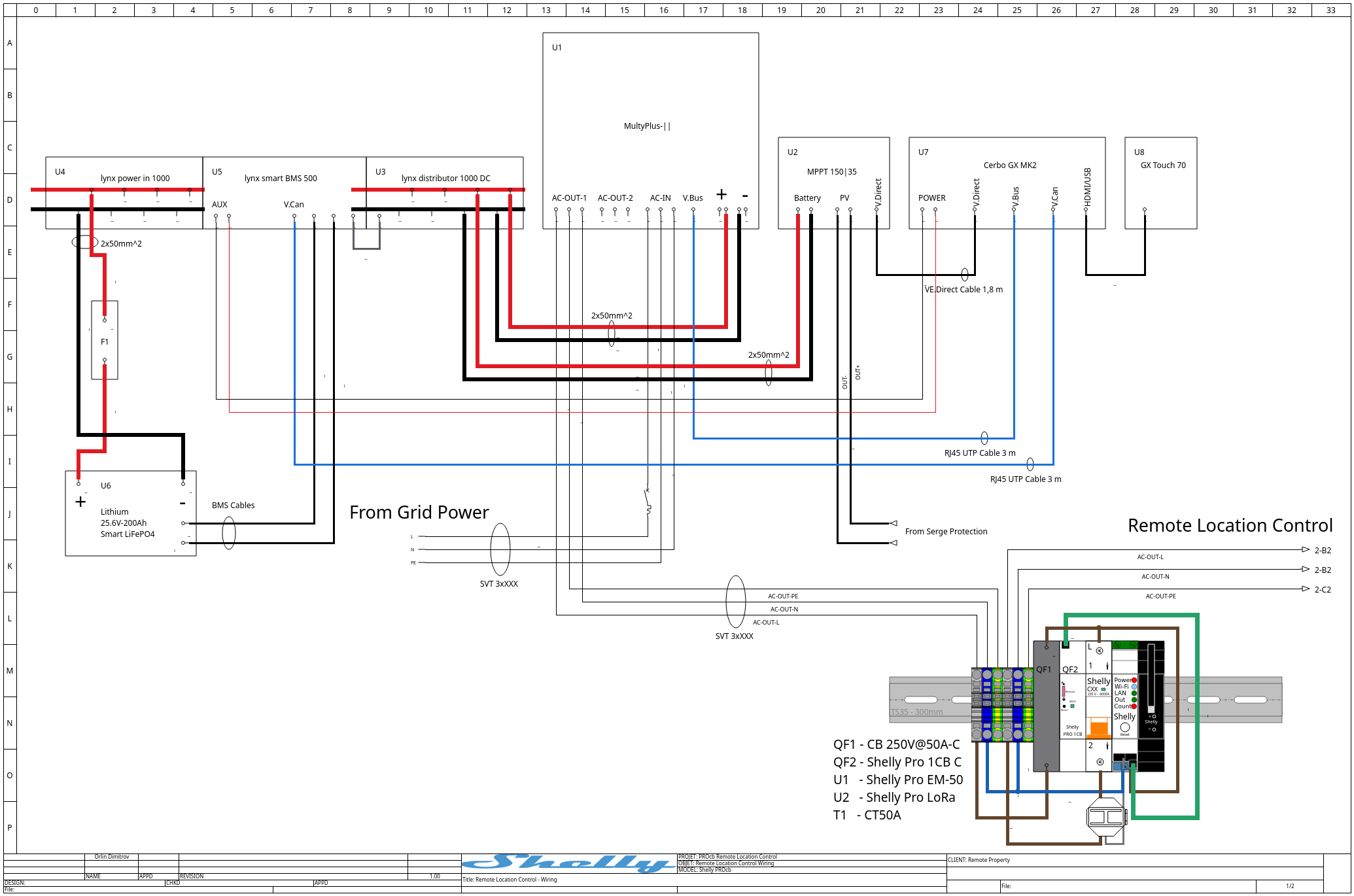
The first schematic folio shows the wider remote-location power system. The Victron installation is the center of the star. From this central system, surplus or available power can be distributed to multiple remote branches.
The schematic also shows the surrounding installation context, including grid input, surge protection, battery, PV/MPPT, inverter/charger equipment, and AC output paths. The Shelly-controlled branch is represented as one controlled remote path from the larger energy system.
This folio answers the question: where does the remote client branch fit in the whole installation?
Folio 2: Client Cabinet Module
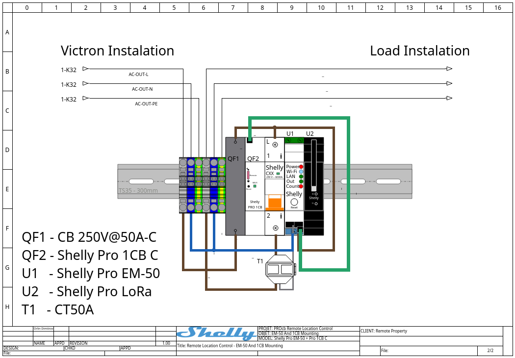
The second folio shows the client-side cabinet. This is the repeatable unit that can be installed at each remote location.
The cabinet contains the Shelly Pro 1CB C, Shelly Pro EM-50, Shelly Pro LoRa Add-on, CT, and terminal blocks. The EM-50 measures the branch current through the CT. The LoRa add-on provides the long-range link back to the central system. The ProCB switches the branch OFF when the prepaid or power-limit logic requires it.
This folio answers the question: what must be installed at each client location?
Control Logic
The remote client script runs on the Shelly Pro EM-50. It periodically reads:
-
EM1.GetStatusfor live voltage, current, and active power; -
EM1Data.GetStatusfor accumulated active energy.
The script calculates consumed energy against the configured prepaid credit. It then applies local policy:
if (state.creditWh <= 0 && !state.lockedOff) { setProCbOutput(false, "prepaid_credit_exceeded"); } if (state.lastPowerW > CONFIG.maxPowerW && !state.lockedOff) { setProCbOutput(false, "power_limit_exceeded"); }
The actual ProCB command is sent over Ethernet from the EM-50 to the ProCB:
proCbRpc("CB.Set", {id: CONFIG.proCbId, output: false}, callback);
The helper uses Shelly HTTP.Request to call the ProCB RPC endpoint:
Shelly.call("HTTP.Request", { method: "POST", url: "http://" + CONFIG.proCbHost + "/rpc/" + method, headers: {"Content-Type": "application/json"}, body: JSON.stringify(params || {}), timeout: 5 });
The central script receives usage reports over LoRa, tracks client state, and can send commands such as:
-
credit_set- assign or renew prepaid credit; -
power_off- disconnect a client branch by policy or operator action; -
allow_reconnect- permit reconnection after the condition is cleared.
Message Flow
-
The remote cabinet boots and announces itself over LoRa.
-
The central controller sends the current prepaid credit value.
-
The EM-50 measures energy and power locally.
-
The remote cabinet periodically sends usage reports to the center.
-
If credit is exhausted or power is exceeded, the remote script commands the ProCB OFF.
-
The remote cabinet reports the ProCB command result back to the center.
-
Reconnection requires an explicit credit/policy update and must not bypass protective-trip handling.
Safety Boundary
The system must clearly distinguish between a commanded OFF state and a protective trip.
A commanded OFF state is a normal control action. It can be caused by prepaid credit exhaustion, a power-limit rule, or a central operator command. Remote reconnection may be allowed when the policy permits it.
A protective trip is different. If the circuit breaker trips because of an electrical fault or protection event, the system must not automatically re-close it. The installation must be inspected, the cause must be understood, and the breaker must be manually re-closed according to the site's safety procedure.
The fail-safe rule is:
If the system cannot prove that OFF was commanded by policy, remote ON remains blocked.
Downloads
Use these files to review or continue the solution implementation:
| File | Download |
|---|---|
| QElectroTech project source | |
| Folio 1 wiring PNG | |
| Folio 2 mounting PNG | |
| System DOT graph | |
| Remote cabinet EM-50 script | |
| Central prepaid LoRa controller script |
Implementation Notes
The scripts are a starting point for the communication design. Before use on real equipment, the following values must be configured per site:
-
client ID;
-
LoRa addresses and encryption settings;
-
ProCB IP address;
-
prepaid credit value;
-
maximum allowed power;
-
reconnection policy;
-
event logging and operator approval workflow.
The LoRa add-on must be enabled and configured on the devices. The ProCB and EM-50 must be reachable over the local Ethernet network inside the client cabinet.
Article Summary
This design turns each remote client cabinet into a measured and controlled branch of a larger Victron-based energy system. The central site distributes available surplus power in a star topology. Each remote cabinet measures its own consumption, communicates through LoRa, and can disconnect itself using Shelly PROcb when prepaid credit or power policy requires it.
The result is a modular pattern for remote energy distribution: central generation and storage, distributed client cabinets, local metering, long-range communication, and controlled branch disconnection.