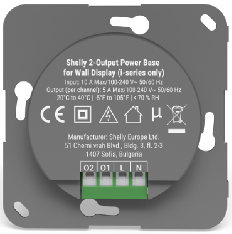
Device identification
-
Device name: Shelly 2-Output Power Base for Wall Display
-
Device model:
Short description
Shelly 2-Output Power Base for Wall Display is a power attachment for Shelly wall displays from the i-series, enabling switching of two output load circuits.
Compatible devices:
-
Shelly Wall Display X1i
-
Shelly Wall Display X2i
Compatibility
-
Shelly Wall Display X1i
-
Shelly Wall Display X2i
Main features
-
Back power supply attachment for Shelly wall displays from the i-series
-
Integrated two relays for light control
Use cases
-
Space-efficient fitting: Install a Shelly Wall Display from the i-series with the Shelly 2-Output Power Base for Wall Display in standard electrical wall boxes for light switches.
-
Light Control: Use it to remotely control and automate the operation of up to two lights.
Main applications
-
Residential
-
MDU (Multi Dwelling Units - apartments, condominiums, hotels, etc.)
-
Light commercial (small office buildings, small retail/restaurant/gas station, etc.)
-
Government/municipal
-
University/college
Simplified internal schematics
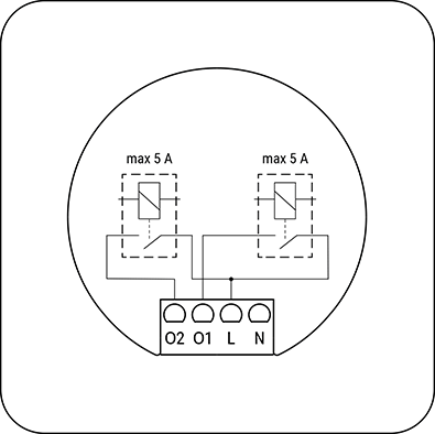
Device electrical interfaces
Inputs
-
2 power supply inputs on screw terminals: N and L
Outputs
-
2 relay output
Supported load types
-
Resistive - incandescent and halogen bulbs
-
Capacitive - LED bulbs, LED drivers, CFL (compact fluorescent lamps)
-
Inductive - LED light transformers
Specifications
| Quantity | Value |
|---|---|
| Physical | |
| Size (HxWxD): | 72.30x69.8x28.70 mm / 2.85x2.75x1.13 inch |
| Weight: | 53.5 g / 1.89 oz |
| Screw terminals max torque: | 0.4 Nm / 3.5 lbin |
| Conductor cross section: | 0.75 to 2.5 mm² / 18 to 14 AWG (solid, stranded, and bootlace ferrules) |
| Conductor stripped length: | 6 to 7 mm / 0.24 to 0.28 inch |
| Mounting: | Wall box |
| Shell material: | Plastic |
| Shell color: | Gray (CMYK: C-0%; M-0%; Y-0%; K-70%) |
| Connectors color: | Green |
| Environmental | |
| Ambient working temperature: | -20 °C to 40 °C / -5 °F to 105 °F |
| Humidity: | 30 % to 70 % RH |
| Max. altitude: | 2000 m / 6562 ft |
| Electrical | |
| Power supply: | 100-240 V~, 50/60Hz |
| Output circuits ratings | |
| Max. switching voltage: | 240 V~ |
| Max. switching current: | 5 A per channel |
| Output: | 5 V⎓, 1 A |
Wiring diagram
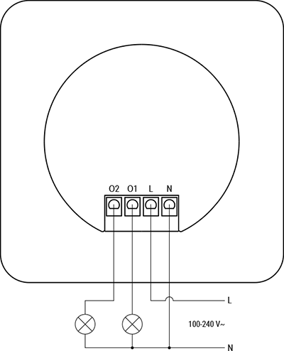
Legend
| Terminals | | Wires | |
|---|---|---|---|
| O2 | Load circuit output terminal 2 | L | Live wire (100-240 V~) |
| O1 | Load circuit output terminal 1 | N | Neutral wire |
| L | Live terminal (100-240 V~) | | |
| N | Neutral terminal | | |
Troubleshooting
…


