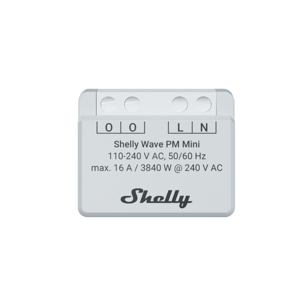
Compact and powerful, this device monitors energy use and fits even in the tightest spaces - now with Z-Wave Long Range for extended wireless coverage and improved network reliability.
*A gateway (smart hub) is not included. It is required to configure Z-Wave Plus devices, and a ZWLR-compatible gateway is mandatory for a device to operate in a ZWLR setting.
3
3 Years Warranty
3 Years Warranty
This warranty covers any issues with the hardware or firmware that exist at the time of purchase or that appear within the warranty period. The warranty includes all parts of the hardware, such as the body, mechanics, and display (if applicable). However, it does not cover consumable items like batteries or accessories, as their lifespan depends on how much they are used.
Supports Z-Wave Long Range - maintains a strong connection over distances exceeding 1 km (line of sight)
Dual Z-Wave frequency options: choose between 864 MHz (ZWLR) or 868.4 MHz ( Z-Wave Plus)
Energy efficient: uses only up to 0.3 W of power
Latest technology: Z-Wave 800 Series
Easy set up with SmartStart - just scan and go
Top level Security, S2 authenticated
Fast and simple installation in most standard electrical boxes and switches
Device identification
Device: Shelly Wave PM Mini (EU) EU Part number/Ordering Code: QTEM-0A1PC16EU Z-Wave Product type ID: 0x0007 Z-Wave Product ID: 0x0081 Z-Wave Manufacturer: Shelly Europe Z-Wave Manufacturer ID: 0x0460
This device supports both Z-Wave® (mesh) and Z-Wave® Long Range (star) network topologies. During the device inclusion process, you must select one type of network topology.
Bellow sections marked with * are valid only for Z-Wave® mesh network inclusion and are not applicable for Z-Wave® Long Range star network inclusion.
Terminology
Click to unhide/hide
OTA - Over-The-Air firmware update.
FW - Firmware
ZAF - Z-Wave® protocol
NIF - Node Information Frame; the frame that is sent at every adding (inclusion) to present/advertise the Device’s capability to the gateway, so that it may adjust its operating ability.
CC - Command Class (ZAF centerpiece of interoperability). The files/processes that determine how data is sent and handled/received. Command Classes include their signatures while sending data to allow recognition of which process is sending data for the destination device.
Switch - A toggle switch or a bi-stable switch.
Push-button - A momentary switch or a monostable switch.
Switch/push-button - It can be a switch or a push-button.
Double press - If the delay between the first and the second press on the switch/push-button is less than 500 ms, this is interpreted as a double press.
Gateway (GW) - A Z-Wave® gateway, also referred to as a Z-Wave® controller, Z-Wave® main controller, Z-Wave® primary controller, or Z-Wave® hub, etc., is a device that serves as a central hub for a Z-Wave® smart home network. The term “gateway” is used in this document.
Mesh network - devices can communicate with each other in addition to the gateway. Devices (only mains powered) can act as repeaters to extend network.
Long range network - devices can communicate only with gateway (no repeater function).
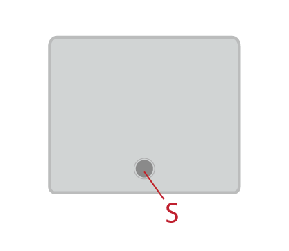
S button - The Z-Wave® Service button, located on Z-Wave® devices and is used for various functions such as adding (inclusion), removing (exclusion), resetting the device to its factory default settings and to switch power output on/off (valid only for Wave Plugs). The term "S button" is used in this document.
Device - In this document, the term “Device” is used to refer to the Shelly Wave device that is a subject of this guide.
End device - Z-Wave end devices are nodes in a Z-Wave network that are not gateways, such as switches, door locks, sensors, etc.
Node ID - The Z-Wave Node ID is a unique identifier assigned at the adding (inclusion) to each device in a Z-Wave network, allowing the network to identify and communicate with this device.
HOME ID - The Z-Wave Home ID is a unique identifier assigned to each Z-Wave network and each device in that network. It distinguishes your Z-Wave network from other networks and ensures that your Z-Wave devices only communicate with devices in your own network.
Adding/Inclusion - The process of adding Z-Wave device to a Z-Wave network - gateway. The words included, added, etc. are used in this regard.
Removing/Exclusion - The process of removing Z-Wave device from a Z-Wave network - gateway. The words excluded, removed, etc. are used in this regard.
Factory reset - After Factory reset, all custom parameters and stored values (kWh, associations, routings, etc.) will return to their default state. The HOME ID and NODE ID assigned to the Device will be deleted. Use this reset procedure only when the gateway is missing or otherwise inoperable.
*Learn mode - a state that allows the Device to receive network information from the gateway.
Normal mode - Is the state of the device which refers to the operational state of a device when it is functioning under regular conditions (switching on/off, dimming, etc.) either during active usage or while in standby mode but still powered.
SmartStart - SmartStart enabled devices can be added (included) to a Z-Wave network by scanning the Z-Wave QR code on the device with a Gateway that supports SmartStart inclusion. The SmartStart enabled device will be automatically added within 10 minutes of being switched on in the vicinity of the Z-Wave network.
MUST - MUST be implemented
OPTIONAL - implement it if time/budget allows
Associations - Associations are used for direct communication between the Device and other devices within your Z-Wave network without the need of the Z-Wave gateway.
Power cycle - Reboot the Device/power supply On/Off of the Device
Blind - Refers to any kind of window treatment, such as venetian blinds, roller blinds (screens), roller shutters, vertical window blinds, curtains, integral venetian blinds, pleated blinds, awnings, etc. Additionally, Wave Shutter can also control window motors, projector screens, or any type of bi-directional AC motor.
Power consumption (W) - refers to the rate at which energy is consumed or used by an electrical device or system. It is measured in watts (W).
Energy consumption (kWh) - refers to the total amount of electrical energy consumed by a device or system over a specific period of time. It is measured in kilowatt-hours (kWh).
Ordering code - The ordering code is the same as the Part number (PN). Where there is not enough space to write the Ordering code, abbreviation PN is used. The PN is written on the DSK label on each device.
Short description
The Device is a small form factor smart power meter, which allows remote monitoring of electric appliances power consumption with a load of up to 16 A.
Use cases
Click to unhide/hide
Power Consumption Monitoring: The primary purpose is to monitor the power consumption of connected devices in real-time. This information can be valuable for understanding energy usage patterns and making informed decisions to reduce consumption.
Energy Efficiency Optimization: Identify energy-hungry appliances and optimize their usage to improve overall energy efficiency in your home or workspace.
Appliance Health Check: Keep track of the power usage of individual appliances to assess their health and performance over time. Sudden spikes or changes in power consumption may indicate issues with the appliance.
Cost Management: With the knowledge of power consumption, you can estimate the cost of running specific devices and manage your electricity expenses more effectively.
Space-Efficient Retrofitting: Integrate the device into standard electrical wall boxes, behind power sockets, light switches, or other locations with limited space.
Remote Monitoring: If Device is connected to the Gateway, it also supports remote access. This allows you to monitor power consumption even when you're away from home.
Basic Functions
SmartStart
Assocciations
Working as Z-Wave repeater
Measuring Voltage (V), Power consumption (W), Energy consumption (kWh), Current (A) of all connected loads.
OTA - Over-The-Air firmware update
Operational Instructions
Click to unhide/hide
Restore after power failure
Restore after power supply failure it takes less than 1 second. In case of the power supply failure, the Device will return output O (O1) to the state defined by value of the Parameter No. 17 after power is restored.
Remote Device reboot Remote Device reboot can be done by Parameter No. 117
Power consumption, Current and Voltage measurement It measures Power consumption (W) and Current (A) of the connected load to the output O (O1). The measured values are sent to Gateway according to Parameters No. 36 and 39 settings.
Energy consumption measurement Energy consumption (kWh) the Device calculate based on measured Power (W) during the time. Energy consumption measurement value is sent to the Gateway when the value increase for 0,1 kWh as unsolicited report. Storing and resetting kWh Store kWh in flash memory immediately after recognizing lost power supply.kWh can be reset by:Factory resetZ-wave command classKWh is not possible to reset with S button. OTA has no influence on kWh stored value, the kWh stored value remains after OTA firmware update.
Z-Wave repeater re-transmits Z-Wave Radio signal by routing the signal around obstacles and radio dead spots to ensure that the signal is received at its intended destinations.
OTA - Over-The-Air firmware update
OTA stands for Over-The-Air, and it refers to the wireless firmware update to end devices
FW version FW version is stored in the Device, also if it is updated by OTA. Firm version is possible to read by the Gateway.
Device serial number Device serial number is stored in the Device after testing in production. Device serial number is possible to read by the Gateway.
Device PART number (PN) Device Part number is stored in the Device after testing in production. Device Part number is possible to read by the Gateway.
Main applications
Residential
MDU (Multi Dwelling Units - apartments, condominiums, hotels, etc.)
Light commercial (small office buildings, small retail/restaurant/gas station, etc.)
Government/municipal
University college
Integrations
Shelly Wave devices are developed on the world's leading technology for smart homes – Z-Wave.
This means Shelly Wave works with all certified gateways supporting Z-Wave communication protocol.
To make sure the functions of Shelly Wave products are supported on your gateway, we are regularly executing compatibility tests of our devices with different Z-Wave gateways.
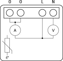
Simplified internal schematics
Device electrical interfaces
Inputs
2 power supply inputs on screw terminals: N , L
Outputs
2 outputs with power measurement on screw terminal
Device has internal Overheat protection. If the temperature exceeds predefined values 80°C for more than 5s, the Device will:
switch off its own output
send the Notification Report to the gateway (Overheat detected)
the LED lights react as specified above (check LED blinking mode for Overheat detected)
The alarm can be reset either by performing a power cycle or, on supported models, by using Parameter 117 – Power Cycle Device, which performs the same function.
NOTE: The Overheat protection is always active and cannot be disabled.
Additional description above under chapter Notification for Overheat detected.
Overcurrent Protection
Device has internal Overcurrent protection. If the current exceeds 16A+10% (Max switching current +10%) for more than 5s, the Device will:
switch off its own output
sends the Notification Report to the gateway (Overcurrent detected)
the LED lights react as specified above (check LED blinking mode for Overcurrent detected)
The alarm can be reset either by performing a power cycle or, on supported models, by using Parameter 117 – Power Cycle Device, which performs the same function.
NOTE: The Over-current protection is always active and cannot be disabled.
Additional description above under chapter Notification for Over-current detected.
Overvoltage Protection
Device has internal Overvoltage protection. This is valid for standard power supply voltage 230 V AC. If the voltage exceeds 240 V AC+15% (278 V AC) for more than 5s, the Device will:
switch off its own output
sends the Notification Report to the Gateway (Overvoltage detected)
the LED lights react as specified above (check LED blinking mode for Overvoltage detected)
The alarm can be reset either by performing a power cycle or, on supported models, by using Parameter 117 – Power Cycle Device, which performs the same function.
NOTE: The Over-voltage protection is always active and cannot be disabled.
Additional description above under chapter Notification for Over-voltage detected.
S button and operating modesSettings mode:Is required to start the desired procedure, for example: adding (inclusion (*not available for Long Range devices)), removing (exclusion), factory reset, etc. It has a limited operating time. After completing the procedure in Setting mode, the Device automatically switches to Normal mode. Entering Setting mode:Press and hold the S button on the Device until the LED turns solid blue.An additional quick press on the S button changes the menu in an infinite loop.The Menu LED status has a timeout of 10s before entering again into Normal mode.S button’s functionsManually adding the Device to a Z-Wave network (*not available for Long Range inclusion)Manually removing the Device from a Z-Wave networkFactory Reset the Device
LED Signalisation
Click to see LED signalisation
General rulesSwitching between Normal and Settings mode is done by press and hold the S button.Solid LED means that you are in the Settings mode (this is not valid for Plugs). Once in settings mode, switch to normal mode goes automatically after 10s.If the LED is not in Alarm mode, it will turn off after a timeout of 30min. Pressing the S button or power cycling the Device will wake the LED for 30min.During module boot up LED will blink in mode 5 (0,2s On blue/0,2s On red) for 4-5 s.Normal mode LED status: Normal mode is defined by stable device function that can remain for an infinite time. LED type: RGB dimmable
Normal mode Removed/ExcludedThe LED will be blinking blue in Mode 1 for 30min after every power cycle and 10min after S button pressed.
Added/IncludedThe LED will be blinking green in Mode 1 for 30min after every power cycle and 10min after S button pressed. Settings in progress
Factory reset and reboot
During factory reset, the LED will turn solid green for approx. 1sec, then the blue and red LED will be blinking 0,1s On / 0,1s Off for about 2sec.
Adding / Removing
During adding or removing, the LED will be blinking blue in Mode 2.
OTA firmware updating
During the OTA update, the LED will be blinking blue and red in Mode 2.
Checking AC or DC voltage power supply
During checking the power supply, the LED will be blinking blue and red in Mode 5.
Settings mode with S button
Adding / Removing menu selected (*adding not available for Long Range inclusion)
When the menu is selected the LED will be on blue, for maximum of 10 seconds.
Adding / Removing menu - while pressing S- button - Add/Remove process selected (*adding not available for Long Range inclusion)
When the menu is executing the LED will be blinking blue in Mode 3.
Factory reset menu selected
When the menu is selected the LED will be on red, for maximum of 10 seconds.
Factory reset - while pressing S - button - Factory reset process selected
When the menu is executing the LED will be blinking red in Mode 3.
Alarm Mode
Overheat detected
The LED will be blinking red in Mode 4
Mode 4 / 2x (LED 0,2s On / 0,2s Off) + 2s Off repeating sequence
LED blinking modes
Click to see the LED blinking modes
LED blinking modes
Mode 1
0,5s On/2s Off
Mode 2
0,5s On/0,5s Off
Mode 3
0,1s On/0,1s Off
Mode 4
(1x to 6x - 0,2s On/0,2s Off) + 2s Off
Mode 5
0,2s On blue/0,2s On red
Technical Specifications
Power supply
110 - 240 V ̴ 50/60 Hz
Power consumption
< 0,3 W
Power measurement (W)
Yes
External protection
16 A, tripping characteristic B or C
6 kA interrupting rating
Energy limiting class 3
Max. measurement power
3840 W
Max. measurement current
16 A
Overheating protection
Yes
Overcurrent protection
Yes
Overvoltage protection
Yes
Long range network
Distance (depends on local condition)
Up to 80 m indoors (262 ft.) or up to 1000 m outdoors (3281 ft.)
Z-Wave® repeater
No
Z-Wave® frequency bands
864 MHz
Mesh network
Distance (depends on local condition)
Up to 40 m indoors (131 ft.)
Z-Wave® repeater
Yes
Z-Wave® frequency bands
868.4 MHz
CPU
Z-Wave® S800
Maximum radio frequency power transmitted in frequency band(s)
< 25 mW
Size (H x W x D)
29x35x16 ± 0.5 mm / 1.11x1.35x0.63 ± 0.02 in
Weight
13 ± 1 g / 0.46 ± 0.04 oz
Mounting
In-wall box
Screw terminals max. torque
0.4 Nm / 3.54 lbin
Conductor cross section
0.2 to 2.5 mm² / 24 to 14 AWG (solid, stranded, and bootlace ferrules)
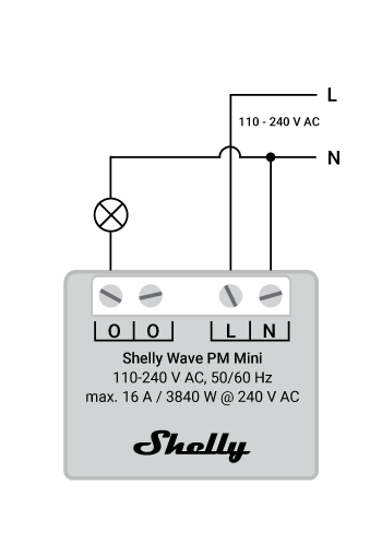
Connect the load-s to the O terminals of the Device and the Neutral wire, as shown on Fig. 1. Connect the Live wire to an L terminal of the Device. Connect the Neutral wire to a N terminal of the Device.
About Z-Wave®
Click to unhide/hide
The Z-Wave® protocol is an interoperable, wireless, RF-based communications technology designed specifically for control, monitoring, and status reading applications in residential and light commercial environments. Mature, proven, and broadly deployed, Z-Wave® is by far the world market leader in wireless control, bringing affordable, reliable, and easy-to-use 'smart' products to millions of people in every aspect of daily life.
Interoperability has always been at the core of the Z-Wave® protocol, alongside the features like backward compatibility, security, and reliability. All Z-Wave® devices can be operated in any Z-Wave® network with other Z-Wave® certified devices, regardless of brand or manufacturer. All mains operated nodes within the network will act as repeaters regardless of vendor to increase the reliability of the network. There are 4000+ Z-Wave® certified products that are backwards- and forwards-compatible in the Z-Wave® ecosystem and well over 100 million devices currently in the market.
With over 20 years in the marketplace, Z-Wave® technology has best-in-class security measures to keep your home network smarter and safer.
Adding and removing the Device to a Z-Wave® network
Click to see how to add, remove and reset the Device
Adding the Device to a Z-Wave® network (inclusion)
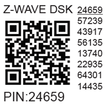
Note!In case of Security 2 (S2) adding (inclusion), a dialog will appear asking you to enter the corresponding PIN Code (5 underlined digits) that are written on the Z-Wave® DSK label on the side of the Device and on the Z-Wave® DSK label inserted in the packaging. IMPORTANT: The PIN Code must not be lost.
SmartStart adding (inclusion)SmartStart enabled products can be added into a Z-Wave® network by scanning the Z-Wave® QR Code present on the Device with a gateway providing SmartStart inclusion. No further action is required, and the SmartStart device will be added automatically within 10 minutes of being switched on in the network vicinity.With the gateway application scan the QR code on the Device label and add the Security 2 (S2) Device Specific Key (DSK) to the provisioning list in the gateway.Connect the Device to a power supply.Check if the blue LED is blinking in Mode 1. If so, the Device is not added to a Z-Wave® network.Adding will be initiated automatically within a few seconds after connecting the Device to a power supply, and the Device will be added to a Z-Wave® network automatically.The blue LED will be blinking in Mode 2 during the adding process.The green LED will be blinking in Mode 1 if the Device is successfully added to a Z-Wave® network.
Adding (inclusion) with the S button (*not available for Long Range inclusion)
Connect the Device to a power supply.
Check if the blue LED is blinking in Mode 1. If so, the Device is not added to a Z-Wave® network.
Enable add/remove mode on the gateway.
To enter the Setting mode, press and hold the S button on the Device until the LED turns solid blue.
Release and then press and hold (> 2s) the S button on the Device until the blue LED starts blinking in Mode 3. Releasing the S button will start the Learn mode.
The blue LED will be blinking in Mode 2 during the adding process.
The green LED will be blinking in Mode 1 if the Device is successfully added to a Z-Wave® network.
Note!In Setting mode, the Device has a timeout of 10s before entering again into Normal mode.
Removing the Device from a Z-Wave® network (exclusion)
Note!The Device will be removed from your Z-Wave® network, but any custom configuration parameters will not be erased.
Removing (exclusion) with the S buttonConnect the Device to a power supply.Check if the green LED is blinking in Mode 1. If so, the Device is added to a Z-Wave® network.Enable add/remove mode on the gateway.To enter the Setting mode, press and hold the S button on the Device until the LED turns solid blue.Release and then press and hold (> 2s) the S button on the Device until the blue LED starts blinking in Mode 3. Releasing the S button will start the Learn mode.The blue LED will be blinking in Mode 2 during the removing process.The blue LED will be blinking in Mode 1 if the Device is successfully removed from a Z-Wave® network.
Note!In Setting mode, the Device has a timeout of 10s before entering again into Normal mode.
Factory reset
Factory reset generalAfter Factory reset, all custom parameters and stored values (kWh, associations, routings, etc.) will return to their default state. HOME ID and NODE ID assigned to the Device will be deleted. Use this reset procedure only when the gateway is missing or otherwise inoperable. Factory reset with the S button
Note! Factory reset with the S button is possible anytime.
To enter the Setting mode, press and hold the S button on the Device until the LED turns solid blue.Press the S button multiple times until the LED turns solid red.Press and hold (> 2s) S button on the Device until the red LED starts blinking in Mode 3. Releasing the S button will start the factory reset.During factory reset, the LED will turn solid green for about 1s, then the blue and red LED will start blinking in Mode 3 for approx. 2s.The blue LED will be blinking in Mode 1 if the Factory reset is successful. Remote factory reset with parameter with a gatewayFactory reset can be done remotely with the settings in Parameter No. 120.
Z-Wave® Security and Device Specific Key (DSK)
Click to see about the Security and the DSK
The Device supports the latest Security 2 (S2) feature. S2 is handled by the strong AES 128 Encryption protocol, which means that the S2 makes Z-Wave® the most secure IoT (Internet of Things) security platform out there. To fully utilize the product and its Security 2 feature, a Security 2-enabled Z-Wave® gateway must be used.
Authenticated Control
Out-Of-Band DSK for adding (inclusion)
May be used by most implementations
The Device also supports Security 2 Authenticated, Unauthenticated, and Unsecure adding (inclusion).
Note! When adding the Device to a Z-Wave® network with a gateway supporting Security 2 (S2), the PIN Code of the Z-Wave® Device Specific Key (DSK) is required. You can find it on the label on the side of the Device and a copy is inserted in the packaging, which must not be lost. Do not remove the Z-Wave® DSK label from the Device. As a backup measure, use the label in the packaging.
The first five digits of the key are highlighted or underlined to help the user identify the PIN Code part of the DSK text. The DSK is additionally represented with a QR Code as shown on the image.
Z-Wave® DSK label and QR code (example)
A joining node requesting to join the S2 Access Control Class or the S2 Authenticated Class will obfuscate its Public Key by setting the bytes 1..2 to zeros (0x00) before transferring its key via RF.
The DSK may be used for out-of-band (OOB) authentication.
The including gateway may use a QR code scanning device to read the entire DSK of the joining device and match it with the obfuscated public key received via RF from the joining device.
Setting Parameters
Click to see some details
Parameter No. 36 - O (O1) Power report on change - percentage
This parameter determines the minimum change in consumed power that will result in sending a new report to the gateway.
Values size: 1 Byte
Default value: 50
Values & descriptions:
0 - reports are disabled
1-100 (1-100%) - change in power
NOTE: When the Device reports the power consumption (W), it will also automatically report the voltage (V) and current (A).
NOTE: Regardless of the power consumption change in percentage, the report will not be sent more frequently than defined by Parameter No. 39.
Parameter No. 39 - Minimum time between reports (O) O1This parameter determines the minimum time that must elapse before a new power report on O (O1) is sent to the gateway.Values size: 1 ByteDefault value: 30 Values & descriptions:0 - reports are disabled1-120 (1-120s) - report interval
NOTE: This Parameter is in relation to Parameter No. 36.
NOTE: Setting the value to less than 30s can cause the Z-Wave network congestion state (slow Device response and decreased network stability).
Parameter No. 117 - Remote Device rebootThis parameter enable restarting or rebooting the Device without physical intervention. Use this parameter only for troubleshooting scope. After device reboot the parameter value will be set to default.Values size: 1 ByteDefault value: 0Values & descriptions:0 - function inactive1 - Remote device reboot
Parameter No. 120 - Factory ResetReset to factory default settings and removed from the Z-Wave network.The parameter is Advanced and may be hidden under the Advanced tag.Values size: 1 ByteDefault value: 0Values & descriptions:0 - No action1 - Factory reset
NOTE: After factory reset is performed, the parameter value is automatically set to 0.
Parameter No. 201 - Serial Number 1This parameter contains a part of device’s serial number.The parameter is Read-Only and cannot be changed. The parameter is Advanced and may be hidden under the Advanced tag.Values size: 4 ByteDefault value: Device specificValues & descriptions:· 0x00000000 - 0x7FFFFFFF Parameter No. 202 - Serial Number 2This parameter contains a part of device’s serial number.The parameter is Read-Only and cannot be changed. The parameter is Advanced and may be hidden under the Advanced tag.Values size: 4 ByteDefault value: Device specificValues & descriptions:· 0x00000000 - 0x7FFFFFFF Parameter No. 203 - Serial Number 3This parameter contains a part of device’s serial number.The parameter is Read-Only and cannot be changed. The parameter is Advanced and may be hidden under the Advanced tag.Values size: 4 ByteDefault value: Device specificValues & descriptions:· 0x00000000 - 0x7FFFFFFF
Command Classes
Click to see the Z-Wave Command Classes
ASSOCIATION_V2 [S0, S2]*
ASSOCIATION_GRP_INFO_V3 [S0, S2]*
CONFIGURATION_V4 [S0, S2]*
DEVICE_RESET_LOCALLY_V1 [S0, S2]*
FIRMWARE_UPDATE_MD_V5 [S0, S2]*
INDICATOR_V3 [S0, S2]*
MANUFACTURER_SPECIFIC_V2 [S0, S2]*
METER_V6 [S0, S2]*
MULTI_CHANNEL_ASSOCIATION_V3 [S0, S2]*
NOTIFICATION_V8 [S0, S2]*
POWERLEVEL_V1 [S0, S2]*
SECURITY_V1
SECURITY_2_V1
SUPERVISION_V1
TRANSPORT_SERVICE_V2
VERSION_V3 [S0, S2]*
ZWAVEPLUS_INFO_V2
[S2]* Security S2 Command Class
Supporting Command Class IndicatorThe Device supports the Command Class Indicator V3 (ID 0x50). When the Device receives an indicator set, the LED blinks according to the received indicator set.Refer to LED Signalization chapter. Supporting Meter Command ClassThe product supports the meter command class and KWh is the default scale report send when the scale type is not present in the received Get.Supported Scale NameScale ValueWatt2KWh0
Notifications Command Class
Click to see the Z-Wave Notification Command Class
Overheat detected
Comment
Overheat detected
Z-Wave Notification Type Name
Heat Alarm
Z-Wave Notification type - Value
0x04
Z-Wave Notification type - Event
State
Z-Wave Notification Name
Overheat detected
Z-Wave Notification Name - Value
0x02
Z-Wave Notification Name - Version
V2
LED signalization
Check LED signalization table
Device reaction - Switch OFF all outputs and send notification
Yes
Action to restore - power cycle
Yes
Action to restore - short press on S button
Yes
Action to restore - press any switch-push button connected to any SW (SW, SW1, SW2, …) terminal
Yes
Over-current detected OCommentOver-current detected O (O1)Z-Wave Notification Type NamePower managementZ-Wave Notification type - Value0x08Z-Wave Notification type - EventStateZ-Wave Notification NameOver-current detectedZ-Wave Notification Name - Value0x06Z-Wave Notification Name - VersionV3LED signalizationCheck LED signalization tableDevice reaction - Switch OFF the output O (O1) and send a notificationYesAction to restore - power cycleYesAction to restore - short press on S buttonYesAction to restore - press any switch-push button connected to any SW (SW, SW1, SW2, …) terminalYes
Over-voltage detectedCommentOver-voltage detectedZ-Wave Notification Type NamePower managementZ-Wave Notification type - Value0x08Z-Wave Notification type - EventStateZ-Wave Notification NameOver-voltage detectedZ-Wave Notification Name - Value0x07Z-Wave Notification Name - VersionV3LED signalizationCheck LED signalization tableDevice reaction - Switch OFF all outputs and send notificationYesAction to restore - power cycleYesAction to restore - short press on S buttonYesAction to restore - press any switch-push button connected to any SW (SW, SW1, SW2, …) terminalYes
Associations
Click to see the Z-Wave Associations
Associations are used for direct communication between the Device and other devices within your Z-Wave network without the need of the Z-Wave gateway. Max. number of associated devices per group is 9. This value is fixed and cannot be configured. Each association group supports the association of up to 9 devices (nodes). To avoid network delays, we recommend limiting the number of associated devices to no more than 5 per group. "Lifeline group" is reserved for controlling devices, such as Gateways and remote controllers, or devices who can interpret the reports sent.Association group 1 – "Lifeline group" sends to the controlling device it's command class notifications and or command class reports when said command classes are triggered. Max. 9 nodes are allowed:
Root device Root device - Association Group 1 - Lifeline
INDICATOR_REPORT : LED status
DEVICE_RESET_LOCALLY_NOTIFICATION : triggered upon request
NOTIFICATION_REPORT : triggered on Overheat
NOTIFICATION_REPORT : triggered on Overcurrent detected O (O1)
NOTIFICATION_REPORT : triggered on Overvoltage detected
METER_REPORT : triggered by load power consumption connected to output O (O1) (according to the settings of Parameters No. 36 and 39)
Disclaimers and Warnings
READ BEFORE USE
This document contains important technical and safety information about the Device, its safe use and installation.
Click to unhide/hide
⚠CAUTION! Danger of electrocution. Mounting/installation of the Device to the power grid must be performed with caution, by a qualified electrician. ⚠CAUTION! Danger of electrocution. Every change in the connections must be done after ensuring there is no voltage present at the Device terminals.⚠CAUTION! Use the Device only with a power grid and appliances that comply with all applicable regulations. A short circuit in the power grid or any appliance connected to the Device may damage it.⚠CAUTION! Do not open the Device. It does not contain any parts that can be maintained by the user. For safety and licensing reasons, unauthorized change and/or modification of the Device is not permitted.⚠CAUTION! The load current circuit has to be secured by a cable protection switch in accordance with EN60898-1 (tripping characteristic B or C, max. 16 A rated current, min. 6 kA interrupting rating, energy limiting class 3).⚠CAUTION! No SELV/PELV circuits may be connected to the terminals of the inputs and outputs, including the extension inputs.⚠CAUTION! Do not connect the Device to appliances exceeding the given max. load!⚠CAUTION! Do not alter the antenna (the antenna must not be shortened, lengthened, or modified in any way!)⚠CAUTION! Connect the Device only in the way shown in these instructions. Any other method could cause damage and/or injury.⚠CAUTION! Do not install the Device where it can get wet.⚠CAUTION! Do not use the Device if it has been damaged!⚠CAUTION! Do not attempt to service or repair the Device yourself!⚠CAUTION! Do not interfere with the Device(any alteration or modification of the Device is prohibited).⚠CAUTION! Before starting the mounting/installation of the Device, check that the breakers are turned off and there is no voltage on their terminals. This can be done with a mains voltage tester or multimeter. When you are sure that there is no voltage, you can proceed to connecting the wires.⚠CAUTION! Do not allow children to play with the push-buttons/ switches connected to the Device. Keep the devices for remote control of Shelly Wave (mobile phones, tablets, PCs) away from children.⚠RECOMMENDATION: Place the antenna as far away as possible from metal elements as they can cause signal interference.⚠RECOMMENDATION: Connect the Device using solid single-core cables or stranded cables with ferrules. The cables should have insulation with increased heat resistance, not less than PVC T105°C (221°F).
Z-Wave® Important disclaimer
Z-wave® wireless communication may not always be 100% reliable. This Device should not be used in situations in which life and/or valuables are solely dependent on its functioning. If the Device is not recognized by your gateway or appears incorrectly, you may need to change the Device type manually and ensure that your gateway supports Z-wave Plus® multi-channel devices and Z-wave® Long Range capability in case of Long Range devices.
Hereby, Shelly Europe Ltd. declares that the radio equipment type Shelly Wave PM Mini is in compliance with Directive 2014/53/ EU, 2014/35/EU, 2014/30/EU, 2011/65/EU. The full text of the EU declaration of conformity is available at the following internet address: https://shelly.link/ShellyWavePMMini_LR-DoC
Disposal & Recycling
Do not dispose of the product in household waste. Recycle the product to prevent environmental and health damage and to promote resource conservation. Dispose of the product at an appropriate waste collection point at your own responsibility.
Resellers, from which the Device was purchased are required to accept Waste Electrical and Electronic Equipment (WEEE) free of charge for proper disposal.
Some electronic products may store personal data. The user is responsible for deleting this data before disposing of the Device. For deletion reset the Device to its factory settings.
Changes in the contact data are published by the Manufacturer at the official website: https://www.shelly.com
Legal Notice
This User Guide is subject to change and improvement without notice. Shelly Wave reserves all rights to revise and update all documentation without any obligation to notify any individual or entity.
Designed with convenience in mind, the Shelly Wave PM Mini packs powerful energy consumption monitoring into a compact, space-saving form factor. It’s perfect for tight spaces where traditional power meters won’t fit. Despite its small size, the Shelly Wave PM Mini delivers reliable performance and full functionality, now enhanced with Z-Wave Long Range support for extended wireless coverage of over 1 km (line of sight) and improved network reliability.
Z-Wave features
Bulletproof security
Security 2 (AES128 encryption) for the utmost safety of your Z-Wave network
Ultra-low power consumption
Most of the Wave devices operate at less than 0.3W
High compatibility
Works with all certified Z-Wave devices and gateways (Z-Wave Plus). ZWLR setting only works with ZWLR-compatible hubs and devices.
Extended wireless range
Up to 40 m indoors (Z-Wave Plus) with signal repeater functionality. ZWLR offers up to 80 m indoor range but connects directly to the hub and does not act as a repeater.
High reliability
Operates on a sub-GHz frequency, ensuring stable and reliable wireless connection without interference
Automatic set-up
SmartStart for automatic inclusion to your
Z-Wave network
Z-Wave device
Z-Wave Gateway
Router
Smartphone
Z-Wave operated
Include the device to your Z-Wave network and control it remotely.
Z-Wave Long Range
The range of the device is exceeding 1 km (line of sight). ZWLR works as a star network.
Power monitoring
Provides precise monitoring of power consumption.
Supports up to 16 A
The device can measure power consumption of a load of up to 16 A.
Wide range of voltage support
Use a wide range of output voltage levels. Supports low voltages.
Smart scenes
Set custom scenes by combining the device with any other Z-Wave devices (gateway required).
Solutions
Shelly Wave PM Mini LR
Stop hidden energy waste
Stop hidden energy waste
Appliance damage often leads to increased energy use without visible signs, quietly wasting energy and money over time. The device detects these spikes instantly, helping you act quickly and avoid costly repairs. Now with Z-Wave Long Range (ZWLR) support, it offers extended wireless coverage and more reliable monitoring.
Optimize energy use with smart metering
Optimize energy use with smart metering
Sometimes we forget to switch off lights or leave unnecessary appliances running overnight, generating wasted energy. The device's power monitoring helps you detect and eliminate excessive energy use of appliances across your household. Together with smart scenes, you can use the device's data to set automations, such as turning off appliances during a power spike to protect them, or during the night to save energy. Thanks to its wireless reach of over 1 km (line of sight), you can reliably monitor your appliances even across large homes, detached garages, or guest houses.
The Shelly z-Wave PM Mini EU LR is definitely brilliant and easy!
as I am really a fan of z-Wave, because it's a reliable Mesh-Network, working more stable than my ZigBee-Network, with all these fancy, unspecified, cheap and funny :-( behaviors!
I love my Shelly Wave PM Mini EU LR Sensors and we have lot's of them, perfectly invisible, small, these are definitely brilliant and easy to install and are perfect for monitoring!
G
G.H.
Don't forget the light !
Very handy. Lets me know if my outdoor lights are on. Very good product.
Choosing a selection results in a full page refresh.










.png?cb=c92ddf6aa3240314704dd967ae11e863)