For DIY users and developers who want to put live Sigenergy data on a Shelly device, or build on top of the Sigenergy OpenAPI. Three working recipes plus full API, Modbus, and MQTT reference.
What you can build
A live Sigenergy plant dashboard mirrored as Virtual Components on a Shelly Pro device. Nine components - five measurements (PV, SOC, battery, grid, load), an on/off-grid indicator, and three status chips (Load, Battery, Operating mode) - appear in the Shelly app, on the device's local web page, and in the Shelly Cloud dashboard, with per-component statistics and event logging.
number:200 PV Power W icon sun-2 bar, 100% = PV array max enum:201 Battery Status icon battery-charge Charging / Idle / Discharging number:201 Battery SOC % icon battery-full bar, 0-100 number:202 Battery Power W icon battery-charge positive = charging boolean:200 On Grid icon plug-circle on-grid / off-grid number:203 Grid Power W icon bolt positive = export enum:200 Load Status icon chart-2 Low / Medium / High / Peak number:204 Load Power W icon home-2 bar, 100% = inverter rated enum:202 Operating Mode icon settings Self-Consumption / AI / TOU / ... All icons use the iconify solar duotone set in Sigen teal (#23D3B4). 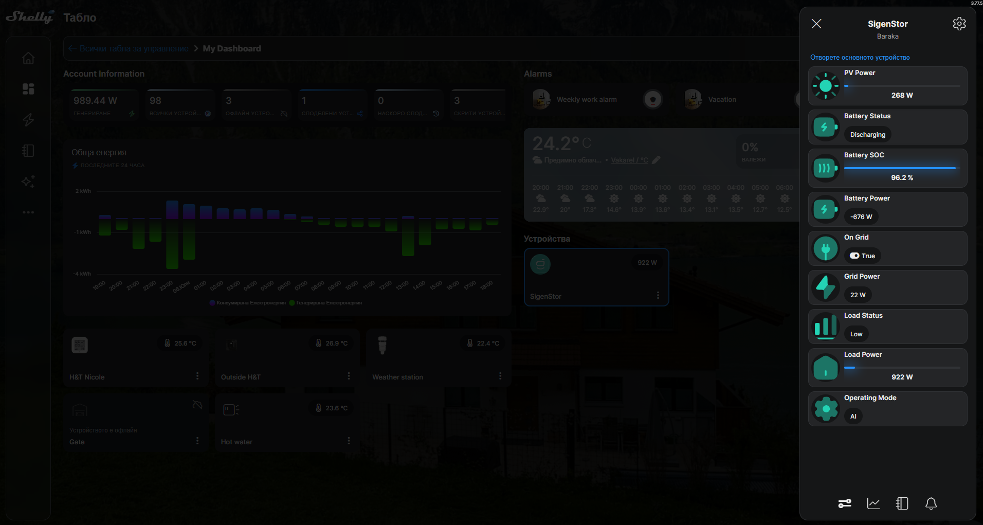
Choosing an approach
The recipes below are alternatives that populate these Virtual Components - run only one at a time, otherwise they overwrite each other. Use this table to pick:
| Approach | How the data gets in | Runs on | Internet / credentials | Update rate | Best for |
|---|---|---|---|---|---|
| A. RS485 Pro add-on (recommended) | The Shelly reads the inverter directly over RS485 (Modbus RTU) and writes its own Virtual Components | The Shelly device itself - no other host at all | None | ~1 s | The most self-contained option: no router, laptop, or cloud. Needs the Shelly Pro and Pro RS485 add-on and a wired connection to the inverter COM port. |
| B. Modbus TCP bridge | Reads Modbus TCP from the inverter over the LAN and pushes values to the Shelly over HTTP | An always-on host on the LAN (open WRT router, mini-PC, Raspberry Pi) | None | 1 s | You already have a small always-on Linux box on the same network and want local data with no extra hardware. |
| C. Cloud data subscription | Sigenergy cloud pushes telemetry to an HTTPS endpoint you host; the Shelly polls that endpoint | A hosted endpoint (serverless function or VM) plus the Shelly | Internet + Sigenergy developer credentials | ~5 min | Remote sites with no local network access, or when you already run cloud infrastructure. |
Recommendation: if you can fit the RS485 add-on, Recipe A is the most robust and self-contained - nothing keeps running except the Shelly itself. Recipe B is a good software-only local option when you already have an always-on box on the LAN. Recipe C is for when only cloud access is available.
Recipe A - Modbus RS485 add-on (fully local, no cloud)
A direct RS485 link from the inverter COM port to a Shelly device fitted with a Modbus RS485 add-on. The Shelly reads the inverter Modbus registers directly and writes them into Virtual Components. No authentication, tokens, developer portal, cloud, or laptop - just wiring and Modbus. This is the recommended long-term setup once you have the hardware.
What you need
-
A Shelly Pro device with the Shelly Pro RS485 add-on.
-
Shelly firmware 2.0.0 or later - the build that exposes the RS485 add-on and the Serial / MbRtuClient component. 2.0.0-beta2 is enough to configure the add-on by RPC / script; the RS485 add-on setup page in the device web interface is officially available from 2.0.0-beta3, so if you set it up through the UI (rather than by script), use beta3 or later.
-
A twisted pair from the add-on A/B terminals to the inverter COM port RS485-1: A+ to pin 15, B- to pin 16, GND to pin 11. (RS485-2, pins 13/14, is reserved for the Sigen energy meter - do not use it.)
-
Modbus enabled on the inverter: set RS485-1 to Modbus RTU Slave in mySigen. Installer profile may need to enable Modbus for the site first.
Confirmed serial parameters
Slave address : 247 (plant address - returns whole-system data) Baud rate : 9600 Framing : 8N1 (8 data bits, no parity, 1 stop bit) Function code : 04 (read input registers) PDU address : the full register number, e.g. 30014 (do not subtract 30001) Shelly setup (all done in the Shelly app or the device web UI - no cloud API involved):
-
Fit the RS485 add-on to the Shelly Pro device, then set the add-on type to RS485.
-
Set the add-on serial port to Modbus Client mode, 9600 8N1 (the parameters above).
-
Add six Virtual Components: five numbers (PV, SOC, battery, grid, load) and one boolean (On-Grid). The ready-made script can also create them for you.
-
Install and start the ready-made script from Downloads below. It reads the plant (slave 247) once per second and updates the Virtual Components. The Shelly Scripts VS Code extension turns this into a one-click Send and Start.
A ready-to-run script (1 s polling, writes VCs 200-204 + boolean 200) is in Downloads below (sigen-monitor-rs485). The register map is in the "Modbus register map" section further down.
Tips
-
Read the plant address 247 for whole-system values (SOC, PV, grid, battery). Individual device addresses (1-246) only return that device own registers.
-
If every read returns
-115 "Invalid server id in response: 0"at all baud rates, the A+/B- pair is reversed - swap the two data wires. -
Keep at least ~1 s between full poll cycles; the inverter expects a minimum request period of about 1 second.
Recipe B - Local Modbus TCP bridge
The Sigenergy system exposes Modbus TCP on port 502 with the inverter as the slave at unit ID 247. On a typical home installation, the inverter is reachable on the home LAN through the gateway. A small Python script on any always-on host on the same LAN - a small router with a Linux distro is a good fit - reads five registers once per second and pushes the values to the Shelly device over HTTP.
-
Polling: 1 second.
-
Cloud: not required.
-
Dependencies: none (Python stdlib only).
-
Auto-start: runs as a system service (
procdon OpenWrt-based routers,systemdon Linux, Scheduled Task on Windows).
Architecture:
sigen-bridge.py -> Modbus TCP -> Sigenergy inverter (:502, Unit ID 247; reached via the gateway on the home LAN) -> Number.Set HTTP POST -> Shelly VCs 200-204 Script: sigen-bridge-router.py (in Downloads below).
Recipe C - Sigenergy data subscription (HTTP push)
Configure the Sigenergy developer portal to push data to an HTTPS endpoint you control, then have the Shelly device poll that endpoint. The full setup lives in the portal: App settings → Data Subscription, mode set to http, with three endpoint URLs (system, telemetry, alarm). Sigenergy then POSTs telemetry on its push cycle (5 minutes by default) and pushes system and alarm data on event.
For displaying live values on a Shelly device, the flow is:
-
In your endpoint, parse the telemetry POST, extract
pvPowerW,storageSOC%,storageChargeDischargePowerW,gridActivePowerW, andinverterActivePowerW. Compute load asinverterActivePowerW + gridActivePowerW. Store the latest values where they can be served back as JSON. -
Expose a GET on your endpoint that returns the cached JSON.
-
Point the Shelly script (
sigen-monitor.jsin Downloads) at the GET URL. The script's Timer polls every 5 minutes and updates Virtual Components 200-204.
How you host the endpoint is up to you: a serverless function, a small VM, an existing internal API, anything that speaks HTTPS and is publicly reachable. A Cloudflare Workers starter is included in Downloads (worker.js, wrangler.toml) as one example.
For the portal-side steps and the activation API call, see Sigenergy's documentation: Application Dashboard → Data Subscription and Subscribe for Telemetry.
API authentication
The Sigenergy OpenAPI uses a key-based auth pair (AppKey + AppSecret), obtained from the developer portal at developer.sigencloud.com → Control Center → Settings. Developer registration requires an invitation code from Sigenergy (approval typically 3-5 days).
POST /openapi/auth/login/key Content-Type: application/json Body: { "key": "" } Response: { "code": 0, "msg": "success", "data": "{\"tokenType\":\"Bearer\",\"accessToken\":\"\",\"expiresIn\":43199}" } The data field is a JSON string, not an object - parse it twice. Token lifetime is ~12 hours; re-request within 5 minutes of expiry.
Include in every subsequent call:
Authorization: Bearer sigen-region: eu Rate limits
-
Energy-flow / realtime endpoints: 1 call per 5 minutes per station.
-
General API: 10 requests per minute for third-party accounts.
Finding the System ID
mySigen → Settings → tap the three-dot menu (upper right). systemId appears in the Basic Info block.
Key endpoints
Energy Flow (real-time)
GET /openapi/systems/{systemId}/energyFlow Fields (all kW except batterySoc):
pvPower - PV generation; always >= 0 gridPower - Grid power; positive = export, negative = import batteryPower - Battery power; positive = charging batterySoc - Battery SoC (%); 0-100 loadPower - Load consumption; always >= 0 evPower - EV charging power heatPumpPower - Heat-pump power System realtime data (generation totals)
POST /openapi/system/realtime/data Body: { "systemId": "" } Returns daily, monthly, annual, and lifetime PV (kWh), plus CO2 / coal-saved / tree-equivalent figures.
Battery command (VPP / NBI)
POST /openapi/system/battery/command Switch the battery between charge, discharge, selfConsumption, and idle modes, with optional limits on charge power, PV use, sell/purchase caps, and priority. Maximum 24 commands per batch per station.
Switch operating mode (NBI only)
POST /openapi/system/operationMode/switch Body: { "systemId": "", "energyStorageOperationMode": 0 } Modes: MSC (0) - Maximum Self-Consumption FFG (5) - Full Feed-in to Grid VPP (6) - VPP mode (service provider only) NBI (8) - North Bound Integration NBI onboarding / offboarding
POST /openapi/board/onboard POST /openapi/board/offboard Body: [ "" ] Result codes: 0 = success, 1401 = already in the requested state (harmless).
Operating modes - quick reference
| Mode | Behaviour |
|---|---|
| MSC | PV → load first; surplus charges battery; grid is last resort. |
| Charge | Charges the battery from PV first, then grid; surplus PV is exported. |
| Discharge | Discharges PV first, then battery - for peak shaving or export. |
| Self-Consumption Grid | Like MSC but surplus goes to the grid, not the battery. |
| Idle | Battery sits; PV surplus is exported. |
| VPP | Service provider controls dispatch; owner cannot change mode. |
| NBI | Designed for third-party integrations; query enabled by default, control requires explicit permission from Sigenergy. |
Modbus register map (TCP and RS485)
Connection (TCP):
Using pymodbus 3.x: PDU address = full register number - do not subtract 30001.
Signal Register Count Type Scale Notes gridPower 30005 2 int32 1 W Positive = import from grid batterySoc 30014 1 uint16 0.1 Divide by 10 for % pvPower 30035 2 int32 1 W batteryPower 30037 2 int32 1 W Positive = charging loadPower 30284 2 int32 1 W The same register map applies over RS485. Confirmed RS485 parameters: slave address 247 (plant), 9600 baud, 8N1, function code 04. See Recipe A above for wiring and Shelly setup.
MQTT telemetry
Broker: mqtts://mqtt-eu.sigencloud.com:8883 Auth: Mutual TLS (ca.pem, client.pem, client.key from Sigenergy) Data topic: {appKey}/openapi/period/{systemId} Activation: publish {accessToken, systemIdList} to openapi/subscription/period Interval: 5 minutes (configurable in developer portal) Push types: Telemetry, Change (status change), Alarm (fault) Telemetry payload includes per-phase grid and inverter power, total PV, storage SoC and power, charge/discharge headroom, plus system status, on/off-grid status, charge/discharge cut-off SoC, and peak-shaving / Storm Watch flags.
Sigenergy's MQTT broker enforces per-subscriber ACLs - mutual-TLS client certificates are scoped to subscribers registered through the developer portal. Plan to receive MQTT in a backend you control, then mirror to Shelly via HTTP.
Downloads
The following files are attached to this page. Click a name to download:
-
sigen-monitor-rs485.shelly.js - Shelly script for the RS485 add-on (Recipe A), enhanced build. Reads the plant over Modbus RTU and creates the Virtual Components (PV, Battery SOC, Battery / Grid / Load power, on/off-grid), plus Load, Battery and Operating-mode status chips. Teal Sigen icons; progress bars only where a real limit exists (PV vs array max, SOC 0-100, Load vs inverter rated) with signed labels for Battery and Grid; per-component cloud logging (Measurement statistics on values, event log on states); all grouped under "Sigenergy SigenStor".
-
sigen-bridge-router.py - Always-on Modbus-TCP bridge (Recipe B).
-
sigen-modbus-bridge.py - Modbus-TCP bridge, PC variant (Recipe B).
-
worker.js - Cloudflare Worker relay (Recipe C).
-
wrangler.toml - Cloudflare Worker config (Recipe C).
-
sigen-monitor.js - Shelly script that polls the Worker URL and updates Virtual Components (Recipe C).
-
sigen-poller.py - Cloud OpenAPI poller (PC alternative).
-
Sigenergy_Modbus_Protocol_V2.7.pdf - Official Sigenergy Modbus protocol: register map, addressing (plant 247), framing.
-
sigen_agent.py - Claude-powered Sigenergy API helper.
-
sigen_agent_README.md - Setup and usage guide for the helper.