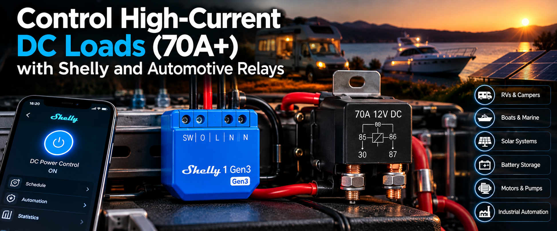
A practical guide to controlling powerful 12V, 24V, and 48V DC devices using Shelly, automotive relays, and DC contactors.
Smart home automation is no longer limited to controlling lights, sockets, and standard household appliances. More and more applications require switching powerful direct-current (DC) loads, from automotive equipment and camper vans to solar installations, off-grid energy systems, and industrial automation.
But what happens when we need to control a device that draws 50A, 70A, or even 100A of DC current?
The solution is surprisingly simple: use Shelly to control an external automotive relay or DC contactor that handles the high-current load.
This approach allows us to integrate powerful DC equipment into the Shelly ecosystem without passing the high current through the Shelly device itself.
In this guide, we'll explore how the solution works, how to select the right components, how to connect everything, and where this approach can be useful.
How Does It Work?
The basic principle is to separate the electrical installation into two independent circuits.
Control Circuit
Shelly controls the electromagnetic coil of an external automotive relay.
The relay coil typically requires only a small amount of current compared to the load being controlled.
Power Circuit
The external relay's high-current contacts switch the power supply to the connected device.
When Shelly turns ON, it energizes the relay coil. The magnetic field closes the relay contacts, allowing current to flow to the load.
When Shelly turns OFF, the coil is de-energized, the relay contacts open, and the load is disconnected.
This way, we can control devices drawing 70A or more, provided that the external relay or contactor is properly rated for the application.
Practical Example
Let's consider a powerful DC device with the following specifications:
| Parameter | Value |
|---|---|
| Supply voltage | 12V DC |
| Operating current | 70A |
| Electrical power | 840W |
| Control device | Shelly 1 Gen3 |
| External switching device | 12V automotive relay / DC contactor |
Instead of switching 70A directly, Shelly only controls the relay coil.
For example, if the relay coil consumes 150mA, Shelly switches just 0.15A, while the external relay handles the 70A power circuit.
The two circuits operate independently and have very different electrical requirements.
This separation is what makes the solution both practical and scalable.
Required Components
For this example, we'll use the following components:
| Component | Purpose |
|---|---|
| Shelly 1 Gen3 | Smart control and automation |
| 12V DC automotive relay | Switching the high-current load |
| Regulated 12V DC power supply | Powering Shelly and the relay coil |
| Flyback diode or suitable suppressor | Protecting against inductive voltage spikes |
| DC-rated fuses | Protecting the control and power circuits |
| Properly sized cables and terminals | Safely carrying the required current |
Why Shelly 1 Gen3?
Shelly 1 Gen3 is particularly suitable for this application because it features potential-free contacts (dry contacts).
This means the relay output can switch an external electrical circuit without that circuit having to share the device's supply voltage.
Shelly 1 Gen3 supports several power supply options, including:
-
12V DC
-
24–48V DC
-
110–240V AC
Its output contacts are rated for up to 10A at 30V DC.
However, this rating does not mean we should directly switch a high-current or highly inductive load.
In our application, Shelly switches only the external relay's control coil.
The external automotive relay handles the actual load current.
Official documentation:
Shelly 1 Gen3 – Knowledge Base
Choosing the Right Automotive Relay
Automotive relays are widely available and commonly used in vehicles, trucks, agricultural machinery, and other DC electrical systems.
They are typically available with four or five terminals.
For a standard four-pin automotive relay, the most common terminal designations are:
| Terminal | Function |
|---|---|
| 85 | Relay coil terminal |
| 86 | Relay coil terminal |
| 30 | Common power contact |
| 87 | Normally open contact (NO) |
Some five-pin relays also include terminal 87a, which represents the normally closed contact (NC).
Always check the wiring diagram of the specific relay because terminal arrangements and internal protection components may vary.
When the correct voltage is applied across terminals 85 and 86, the electromagnetic coil activates and closes the connection between terminals 30 and 87.
Can an Automotive Relay Really Handle 70A?
Yes.
There are automotive relays specifically designed for high-current applications.
For example, TE Connectivity manufactures automotive power relays with contact ratings reaching 70A.
A representative product from its automotive relay portfolio is:
TE Connectivity – Power Relay F Series
These relays are available in configurations designed for automotive power distribution applications.
Manufacturer:
TE Connectivity – Automotive Relays
However, there is an important consideration.
A relay marked "70A" is not automatically suitable for switching every 70A DC load.
When selecting a relay, we must consider:
-
Continuous current rating
-
Maximum DC switching voltage
-
Making and breaking current
-
Load characteristics
-
Inrush current
-
Operating temperature
-
Expected switching frequency
-
Electrical lifetime
For example, switching a resistive heating element is very different from switching a DC motor or an inverter with large input capacitors.
For applications involving frequent switching or continuous high-current operation, a dedicated DC contactor may be the better choice.
Electrical Wiring
Let's build a simple example using:
-
Shelly 1 Gen3
-
Regulated 12V DC power supply
-
Four-pin automotive relay with a 12V coil
-
12V DC load drawing up to 70A
We will separate the wiring into the control circuit and the power circuit.
Control Circuit
REGULATED 12V DC │ ┌──────────┴──────────┐ │ │ ▼ ▼ Shelly 1 Gen3 Fuse F1 12V (+) │ │ ▼ Relay Terminal 86 │ [ COIL ] │ Relay Terminal 85 │ ▼ Shelly O Shelly I ─────────────── 0V / GND Shelly GND ───────────── 0V / GND In this configuration, the Shelly dry contact (I–O) switches the negative side of the relay coil.
When Shelly turns ON, the contact closes, completing the coil circuit.
The automotive relay is then activated.
A suitable suppression device must be connected across the relay coil to protect the switching contacts against inductive voltage spikes.
Power Circuit
12V DC BATTERY (+) │ │ Fuse F2 │ │ ▼ Relay Terminal 30 │ [ CONTACT ] │ Relay Terminal 87 │ │ ▼ DC LOAD 70A │ │ ▼ BATTERY (-) The high-current path is completely separate from Shelly.
The 70A current flows through the external relay, power wiring, and load — never through the Shelly device.
This is the fundamental advantage of using an external relay or contactor.
The diagrams illustrate the operating principle. Cable sizing, fuse selection, terminals, and protection devices must be designed for the actual installation.
Protecting the Relay Coil
There is one important technical detail that should not be overlooked.
An automotive relay contains an electromagnetic coil.
This coil is an inductive load.
When the supply is disconnected, the magnetic field collapses and can generate a short voltage spike.
Without proper protection, this voltage spike can cause arcing at the Shelly contacts and potentially reduce their lifespan.
Flyback Diode Protection
One common solution is to connect a flyback diode across the relay coil.
For a standard 12V DC coil without built-in suppression:
-
Connect the diode cathode (marked end) to terminal 86 (+).
-
Connect the diode anode to terminal 85 (−).
The diode must be appropriately rated for the coil current and stored inductive energy.
However, there is an important limitation.
A conventional flyback diode slows down the release of the relay.
For high-current DC switching, a slower release may increase contact arcing and wear.
For this reason, a manufacturer-approved suppression circuit using a Zener diode, TVS device, or another suitable method may be preferable.
Some automotive relays already include internal suppression components.
Always check the manufacturer's specifications before adding external protection.
Technical reference:
TE Connectivity – Relay Coil Suppression
Controlling the Relay with Shelly Smart Control
Once the electrical installation has been completed and verified, the control process is straightforward.
Add Shelly 1 Gen3 to the Shelly Smart Control application.
Give it a descriptive name, such as:
DC Power Control
Now, whenever the Shelly output is activated, the external automotive relay will switch the connected load.
ON Command
When the Shelly relay turns ON:
-
Shelly closes its dry contact.
-
Current flows through the external relay coil.
-
The automotive relay activates.
-
The power contacts close.
-
The high-current DC load receives power.
OFF Command
When the Shelly relay turns OFF:
-
The dry contact opens.
-
The external relay coil is de-energized.
-
The power contacts open.
-
The DC load is disconnected.
This provides remote control of powerful DC equipment through the Shelly ecosystem.
Local HTTP API Control
Shelly also supports local control through its RPC API.
To turn the relay ON:
http://SHELLY_IP/rpc/Switch.Set?id=0&on=true To turn the relay OFF:
http://SHELLY_IP/rpc/Switch.Set?id=0&on=false Replace SHELLY_IP with the actual IP address of your device.
These commands can be used with:
-
Home Assistant
-
Node-RED
-
Custom automation software
-
Local web applications
-
Industrial control systems
Because the commands work over the local network, cloud connectivity is not required.
Official API documentation:
Recommended Power-On Settings
For applications where the safe state is OFF, consider configuring the Shelly output with:
Power-on default: OFF
This helps prevent the external relay from activating automatically after a power interruption.
However, the complete system must still be designed to handle power failures, unexpected restarts, and communication interruptions safely.
Real-World Applications
The ability to control high-current DC loads opens up many interesting possibilities.
Camper Vans and RVs
Camper vans and recreational vehicles typically use 12V or 24V electrical systems.
With Shelly and suitable automotive relays, we can automate equipment such as:
-
Auxiliary lighting
-
Ventilation systems
-
Water pumps
-
DC heating equipment
-
Additional electrical accessories
-
Selected auxiliary power circuits
For example, a Shelly automation could activate an auxiliary ventilation system based on temperature.
A separate high-current relay would handle the actual electrical load.
Boats and Marine Applications
Many marine electrical systems operate at 12V or 24V DC.
Using appropriately rated DC relays or contactors, Shelly can help automate:
-
Cabin lighting
-
Ventilation
-
Water pumps
-
Auxiliary equipment
-
Selected DC distribution circuits
Marine installations require additional consideration of moisture, corrosion, vibration, and applicable electrical safety standards.
Equipment must be suitable for the specific marine environment.
Solar and Off-Grid Energy Systems
Off-grid energy installations often require intelligent control of electrical loads.
For example, imagine a solar installation with battery storage.
We may want to disconnect a non-essential DC load when the battery state of charge drops below a specific threshold.
Using Shelly together with Home Assistant, we could create automation logic such as:
Battery SOC > 80%
Enable selected auxiliary DC loads.
Battery SOC < 30%
Disconnect those loads to preserve battery capacity.
Shelly would control the external DC contactor, while Home Assistant would provide the automation logic.
This approach allows us to integrate energy management with physical electrical switching.
For battery systems involving inverters or equipment with large input capacitors, a suitable precharge circuit may also be required.
A standard automotive relay is not necessarily suitable for directly connecting such loads.
Industrial Automation
The same principle can be applied in industrial installations.
Examples include:
-
DC motors
-
Electromagnetic valves
-
DC heating elements
-
Pumps
-
Auxiliary power circuits
-
Other high-current equipment
The switching device must always be selected according to the electrical characteristics and operating conditions of the load.
What About 24V, 48V, or Higher DC Voltages?
The operating principle remains the same.
Shelly controls a low-power relay coil, while the external relay or contactor handles the high-current circuit.
However, there is an important difference when increasing the DC voltage.
A relay designed for switching 12V DC must not automatically be assumed suitable for switching 48V DC.
Unlike alternating current, direct current does not naturally cross zero.
In AC circuits, the periodic zero crossing helps extinguish the electrical arc that forms when contacts open.
In DC circuits, this natural zero crossing does not occur.
As a result, the electrical arc can be more difficult to extinguish.
As voltage and current increase, the ability of the switching device to safely interrupt the circuit becomes increasingly important.
Example: 48V DC System
Imagine a 48V battery installation with a load requiring 70A.
The approximate load power is:
48V × 70A = 3,360W
This is significantly more demanding than a 12V / 70A installation.
For this application, we should use a DC contactor specifically rated to switch the actual voltage, current, and load type.
Interestingly, the contactor can still have a 12V control coil.
This means we can use a regulated 12V power supply for the Shelly control circuit while the contactor switches the separate 48V power circuit.
The two circuits do not need to operate at the same voltage.
This flexibility makes dry-contact Shelly devices useful for integrating different electrical systems.
Important Safety Considerations
Working with currents of 70A or more requires careful electrical design.
Even at relatively low voltages, high currents can generate significant heat if cables, connections, or switching devices are incorrectly sized.
Several precautions are essential.
Proper Circuit Protection
Always use appropriately rated DC fuses or circuit protection devices.
The main fuse should be installed as close as practical to the power source, according to the installation design.
The relay control circuit should also have suitable protection.
Correct Cable Sizing
Select power cables based on:
-
Maximum operating current
-
Cable length
-
Installation method
-
Ambient temperature
-
Acceptable voltage drop
-
Applicable electrical standards
Do not select cable size based only on the relay's advertised current rating.
Appropriate Switching Device
Make sure the selected relay or contactor is rated for:
-
The actual DC operating voltage
-
Continuous current
-
Switching current
-
Load characteristics
-
Expected switching frequency
-
Environmental conditions
A nominal 70A rating alone is not sufficient to establish suitability.
Stable Power Supply
Shelly 1 Gen3 requires a suitable regulated power supply when operated at 12V DC.
This is particularly important in automotive environments, where the electrical system may experience voltage fluctuations and transient spikes.
Shelly 1 Gen3 is not an automotive-certified control module, and its specified operating temperature range is −20°C to +40°C.
Therefore, the installation environment must be considered carefully.
Additional Load Protection
Motors, inverters, capacitive loads, and other electrical equipment may require additional protective circuits.
These can include appropriate transient suppression, precharge circuits, motor protection, and dedicated safety devices.
Do Not Replace Safety Systems
Shelly provides control and automation functionality.
It should not be used as a replacement for:
-
Circuit protection
-
Battery management systems
-
Emergency stop circuits
-
Safety-rated disconnect devices
-
Other mandatory protective equipment
For high-current installations, the complete electrical design should be reviewed and verified by a qualified professional before commissioning.
Conclusion
Controlling powerful DC loads does not necessarily require complex electronics or expensive control systems.
By combining Shelly 1 Gen3 with an appropriately rated automotive relay or DC contactor, we can extend smart automation to electrical equipment operating at tens or even hundreds of amperes.
The key is separating the control circuit from the power circuit.
Shelly provides the intelligence:
-
Remote ON/OFF control
-
Scheduling
-
Local API integration
-
Home Assistant compatibility
-
Node-RED automation
-
Integration with other Shelly devices
The external relay or contactor handles the actual power switching.
This creates a flexible architecture that can be adapted to many applications, including camper vans, boats, solar installations, off-grid energy systems, and industrial equipment.
For a simple 12V / 70A installation, a properly selected automotive relay may be sufficient.
For higher DC voltages, demanding loads, or frequent switching, a dedicated DC contactor is generally a more appropriate solution.
The important point is that Shelly does not need to carry the full load current to control powerful electrical equipment.
Sometimes, all we need is a small smart relay controlling a much larger one.
And that is one of the simplest ways to bring high-current DC equipment into the Shelly ecosystem.
Useful References
Shelly Documentation
Shelly 1 Gen3 – Official Knowledge Base
Shelly RPC API – Switch Control
Relay and Electrical Design
TE Connectivity – Relays and Contactors
TE Connectivity – Relay Coil Suppression
We Value Your Feedback!
Thank you for taking the time to read our article! Was it helpful or interesting?
Your insights can help us improve. We’d be grateful for any feedback. If you have a moment,
please share it with us at the following email:


