Note: The product line known as "Shelly Qubino Wave" will now be referred to as "Shelly Wave". This name change will not impact the functionality of any devices. The only modification will be the use of the new name in all future documentation.
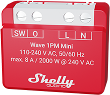
Device identification
Device name: Wave 1PM Mini
AUS Part number/Ordering Code: QMSW-0A1P8AU
Z-Wave Product type ID: 0x0002
Z-Wave Product ID: 0x008F
Z-Wave Manufacturer: Shelly Europe Ltd.
Z-Wave Manufacturer ID: 0x0460
Terminology
-
Device - In this document, the term “Device” is used to refer to the Shelly Qubino device that is a subject of this guide.
-
Gateway - A Z-Wave® gateway, also referred to as a Z-Wave® controller, Z-Wave® main controller, Z-Wave® primary controller, or Z-Wave® hub, etc., is a device that serves as a central hub for a Z-Wave® smart home network. The term “gateway” is used in this document.
-
S button - The Z-Wave® Service button, located on Z-Wave® devices and is used for various functions such as adding (inclusion), removing (exclusion), and resetting the device to its factory default settings. The term "S button" is used in this document.
Short description
The Device is a small form factor smart switch with power measurement. It controls the on/off function for one electrical appliance with a load of up to 8 A AC, such as a bulb, ceiling fan, or IR heater. It is compatible with switches (default) and push-buttons.
If the SW (SW1) is configured as a switch (default), each toggle of the switch will change the output O (O1) state to the opposite state - on, off, on, etc. If the SW (SW1) is configured as a push-button in the Device settings, each press of the push-button will change the output O (O1) state to the opposite state - on, off, on, etc.
If the SW (SW1) is configured as a switch (default), each toggle of the switch will change the output O (O1) state to the opposite state - on, off, on, etc.
If the SW (SW1) is configured as a switch-memory, than:
-
Switching to Close switch-memory contact: Change the state of the output state O (O1) to the On state and send command to the associated devices in associated groups 2 and 3 (check chapter Z-Wave Association)
-
Switching to Open switch-memory contact: Change the state of the output state O (O1) to the Off state and send command to the associated devices in associated groups 2 and 3 (check chapter Z-Wave Association)
If the SW (SW1) is configured as a push-button in the Device settings, each press of the push-button changes the output state O (O1) to opposite - ON, OFF, ON, etc.
-
1x click: Change the state of the output state O (O1) to the opposite one and send command to the associated devices in associated groups 2 and 3 (check chapter Z-Wave Association)
-
2x click: If the delay between first in second click is less then 500ms, this is interpreted as double clik. Send command to the associated devices (dimmers, shutters,….) in associated groups 2 and 3 (check chapter Z-Wave Association)
-
Hold: Send command to the associated devices in associated group 3 (check chapter Z-Wave Association)
-
Release: Send command to the associated devices in associated group 3 (check chapter Z-Wave Association)
Main applications
-
Residential
-
MDU (Multi Dwelling Units - apartments, condominiums, hotels, etc.)
-
Light commercial (small office buildings, small retail/restaurant/gas station, etc.)
-
Government/municipal
-
University/college
Integrations
Shelly Qubino Wave devices are developed on the world's leading technology for smart homes – Z-Wave.
This means Shelly Qubino Wave works with all certified gateways supporting Z-Wave communication protocol.
To make sure the functions of Shelly Qubino Wave products are supported on your gateway, we are regularly executing compatibility tests of our devices with different Z-Wave gateways.
Simplified internal schematics
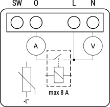
Device electrical interfaces
Outputs
Addon interface
N/A
Connectivity
Z-Wave - Unsecure, S0 Security, S2 Unauthenticated Security, S2 Authenticated Security
Safety features
Overheat protection
Any of next activities reset this alarm: power cycle, short press on S button, press any switch-push button connected to any SW (SW, SW1, SW2, …) terminal.
NOTE: The Overheat protection is always active and cannot be disabled.
Additional description above under chapter Notification for Overheat detected.
Over-current Protection
Device has internal Over-current protection. If the current exceeds 16A+10% (Max switching current +10%) for more than 5s, the Device will:
Any of the following activities reset this alarm: power cycle, short press on the S button, press on any switch/push-button connected to any SW (SW, SW1, SW2, …) terminal.
NOTE: The Over-current protection is always active and cannot be disabled.
Additional description above under chapter Notification for Over-current detected.
Over-voltage Protection
Device has internal Over-voltage protection. This is valid for standard power supply voltage 230 V AC. If the voltage exceeds 240 V AC+15% (278 V AC) for more than 5s, the Device will:
Any of the following activities reset this alarm: power cycle, short press on the S button, press on any switch/push-button connected to any SW (SW, SW1, SW2, …) terminal.
NOTE: The Over-voltage protection is always active and cannot be disabled.
Additional description above under chapter Notification for Over-voltage detected.
Supported load types
-
Resistive (incandescent bulbs, heating devices)
-
Capacitive (capacitor banks, electronic equipment, motor start capacitors)
-
Inductive with RC Snubber (LED light drivers, transformers, fans, refrigerators, air-conditioners)
User interface
-
Normal mode
-
Setting in progress mode
-
Setting mode (with S button)
-
Settings mode is required to start desired procedure for example: adding (inclusion), removing (exclusion), factory reset etc. It has a limited time of operation. After the procedure in Setting mode is concluded, the Device goes automatically into Normal mode.
-
Entering to Setting mode:
-
Quickly press and hold the S button on the Device until the LED turns solid blue
-
An additional quick press on the S button means menu change in infinite loop
-
Menu LED status has a timeout of 10s before entering again into Normal state
LED Signalisation
Click to see the LED Signalisation
Normal mode
Removed/Excluded
The LED will be blinking blue in Mode 1 for 10 min after every power cycle and 10 min after S button pressed.

Added/Included
The LED will be blinking green in Mode 1 for 10 min after every power cycle and 10 min after S button pressed.

Settings in progress
Factory reset and reboot
During factory reset, the LED will turn solid green for approx. 1sec, then the blue and red LED will be blinking 0,1s On, 0,1s Off for about 2sec.
Adding / Removing
During adding or removing, the LED will be blinking blue in Mode 2.

Firmware updating OTA
During the OTA update, the LED will be blinking blue and red in Mode 2.

Checking power supply 230 V AC frequency or 24 V DC voltage
During checking the power supply, the LED will be blinking blue and red in Mode 5.

Adding / Removing menu selected
When the menu is selected the LED will be on blue, for maximum of 10 seconds.
Adding / Removing menu - while pressing S- button - Add/Remove process selected
When the menu is executing the LED will be blinking blue in Mode 3.

Factory reset menu selected
When the menu is selected the LED will be on red, for maximum of 10 seconds.
Factory reset - while pressing S - button - Factory reset process selected
When the menu is executing the LED will be blinking red in Mode 3.

Alarm Mode
Over-current detected
The LED will be blinking red in Mode 4 1x - 0,2s On 0,2s Off 2s Off and repeating this sequence

Overheat detected
The LED will be blinking red in Mode 4 2x - 0,2s On 0,2s Off 0,2s On 0,2s Off 2s Off and repeating this sequence

Power supply fault (power supply 230 V AC frequency or 24 V DC voltage fault)
The LED will be blinking red in Mode 4 3x - 0,2s On 0,2s Off 0,2s On 0,2s Off 0,2s On 0,2s Off 2s Off and repeating this sequence

LED blinking modes
Click to see the LED blinking modes
| LED blinking modes |
| Mode 1 | 0,5s On/2s Off |
| Mode 2 | 0,5s On/0,5s Off |
| Mode 3 | 0,1s On/0,1s Off |
| Mode 4 | (1x to 6x - 0,2s On/0,2s Off) + 2s Off |
| Mode 5 | 0,2s On blue/0,2s On red |
Specifications
| Power supply | 110 - 240 V ̴ 50/60 Hz |
| Power consumption | < 0,3W |
| Power measurement [W] | Yes |
| External protection | 10 A, tripping characteristic B or C 6 kA interrupting rating Energy limiting class 3 |
| Max. switching voltage AC | 240 V |
| Max. switching current AC | 8 A |
| Max switching power AC: | 2000 W |
| Max. switching voltage DC | N/A |
| Max. switching current DC | N/A |
| Overheating protection | Yes |
| Overcurrent protection | Yes |
| Overvoltage protection | Yes |
| Distance | Up to 40 m indoors (131 ft.) (depends on local condition) |
| Z-Wave® repeater: | Yes |
| CPU | Z-Wave® S800 |
| Z-Wave® frequency bands: | 919.8 MHz |
| Maximum radio frequency power transmitted in frequency band(s) | < 25 mW |
| Size (H x W x D) | 29x35x16 ± 0.5 mm / 1.11x1.35x0.63 ± 0.02 in |
| Weight | 18 ± 1 g / 0.63 ± 0.04 oz |
| Mounting | In-wall box |
| Screw terminals max. torque | 0.4 Nm / 3.54 lbin |
| Conductor cross section | 0.2 to 2.5 mm² / 24 to 14 AWG (solid, stranded, and bootlace ferrules) |
| Conductor stripped length | 6 to 7 mm / 0.24 to 0.28 in |
| Shell material | Plastic |
| Color | Red |
| Ambient temperature | -20°C to 40°C / -5°F to 105°F |
| Humidity | 30% to 70% RH |
| Max. altitude | 2000 m / 6562 ft. |
Basic wiring diagram
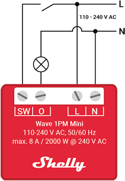
Legend
| Terminals | | Cables | |
| N | Neutral terminal | N | Neutral wire |
| L | Live terminal (110–240 V AC) | L | Live (110 - 240 VAC) wire |
| SW | Switch/push-button input terminal (controlling O) | | |
| I | Load circuit input terminal | S | S button |
| O | Load circuit output terminal | | |
About Z-Wave®
Adding the Device to a Z-Wave® network (inclusion)
Click to see how to add, remove and reset the Device
Note! All Device outputs (O, O1, O2, etc. - depending on the Device type) will turn the load 1s on/1s off /1s on/1s off if the Device is successfully added to/removed from a Z-Wave® network.
Note! In case of Security 2 (S2) adding (inclusion), a dialog will appear asking you to enter the corresponding PIN Code (5 underlined digits) that are written on the Z-Wave® DSK label on the side of the Device and on the Z-Wave® DSK label inserted in the packaging.
IMPORTANT: The PIN Code must not be lost.
SmartStart adding (inclusion)
SmartStart enabled products can be added into a Z-Wave® network by scanning the Z-Wave® QR Code present on the Device with a gateway providing SmartStart inclusion. No further action is required, and the SmartStart device will be added automatically within 10 minutes of being switched on in the network vicinity.
-
With the gateway application scan the QR code on the Device label and add the Security 2 (S2) Device Specific Key (DSK) to the provisioning list in the gateway.
-
Connect the Device to a power supply.
-
Check if the blue LED is blinking in Mode 1. If so, the Device is not added to a Z-Wave® network.
-
Adding will be initiated automatically within a few seconds after connecting the Device to a power supply, and the Device will be added to a Z-Wave® network automatically.
-
The blue LED will be blinking in Mode 2 during the adding process.
-
The green LED will be blinking in Mode 1 if the Device is successfully added to a Z-Wave® network.
-
Connect the Device to a power supply.
-
Check if the blue LED is blinking in Mode 1. If so, the Device is not added to a Z-Wave® network.
-
Enable add/remove mode on the gateway.
-
To enter the Setting mode, quickly press and hold the S button on the Device until the LED turns solid blue.
-
Quickly release and then press and hold (> 2s) the S button on the Device until the blue LED starts blinking in Mode 3. Releasing the S button will start the Learn mode.
-
The blue LED will be blinking in Mode 2 during the adding process.
-
The green LED will be blinking in Mode 1 if the Device is successfully added to a Z-Wave® network.
Note! In Setting mode, the Device has a timeout of 10s before entering again into Normal mode.
-
Connect the Device to a power supply.
-
Check if the blue LED is blinking in Mode 1. If so, the Device is not added to a Z-Wave® network.
-
Enable add/remove mode on the gateway.
-
Toggle the switch/push-button connected to any of the SW terminals (SW, SW1, SW2, etc.) 3 times within 3 seconds (this procedure puts the Device in Learn mode*). The Device must receive on/off signal 3 times, which means pressing the momentary switch 3 times, or toggling the switch on and off 3 times.
-
The blue LED will be blinking in Mode 2 during the adding process.
-
The green LED will be blinking in Mode 1 if the Device is successfully added to a Z-Wave® network.
*Learn mode - a state that allows the Device to receive network information from the gateway.
Removing the Device from a Z-Wave® network (exclusion)
Note! The Device will be removed from your Z-Wave® network, but any custom configuration parameters will not be erased.
Note! All Device outputs (O, O1, O2, etc. - depending on the Device type) will turn the load 1s on/1s off /1s on/1s off if the Device is successfully added to/removed from a Z-Wave® network.
-
Connect the Device to a power supply.
-
Check if the green LED is blinking in Mode 1. If so, the Device is added to a Z-Wave® network.
-
Enable add/remove mode on the gateway.
-
To enter the Setting mode, quickly press and hold the S button on the Device until the LED turns solid blue.
-
Quickly release and then press and hold (> 2s) the S button on the Device until the blue LED starts blinking in Mode 3. Releasing the S button will start the LEARN MODE.
-
The blue LED will be blinking in Mode 2 during the removing process.
-
The blue LED will be blinking in Mode 1 if the Device is successfully removed from a Z-Wave® network.
Note! In Setting mode, the Device has a timeout of 10s before entering again into Normal mode.
-
Connect the Device to a power supply.
-
Check if the green LED is blinking in Mode 1. If so, the Device is added to a Z-Wave® network.
-
Enable add/remove mode on the gateway.
-
Toggle the switch/push-button connected to any of the SW terminals (SW, SW1, SW2,…) 3 times within 3 seconds (this procedure puts the Device in LEARN MODE). The Device must receive on/off signal 3 times, which means pressing the momentary switch 3 times, or toggling the switch on and off 3 times.
-
The blue LED will be blinking in Mode 2 during the removing process.
-
The blue LED will be blinking in Mode 1 if the Device is successfully removed from a Z-Wave® network.
Factory reset
Factory reset general
After Factory reset, all custom parameters and stored values (kWh, associations, routings, etc.) will return to their default state. HOME ID and NODE ID assigned to the Device will be deleted. Use this reset procedure only when the gateway is missing or otherwise inoperable.
Note! Factory reset with the S button is possible anytime.
-
To enter the Setting mode, quickly press and hold the S button on the Device until the LED turns solid blue.
-
Press the S button multiple times until the LED turns solid red.
-
Press and hold (> 2s) S button on the Device until the red LED starts blinking in Mode 3. Releasing the S button will start the factory reset.
-
During factory reset, the LED will turn solid green for about 1s, then the blue and red LED will start blinking in Mode 3 for approx. 2s.
-
The blue LED will be blinking in Mode 1 if the Factory reset is successful.
Note! Factory reset with a switch/push-button is only possible within the first minute after the Device is connected to a power supply.
-
Connect the Device to a power supply.
-
Toggle the switch/push-button connected to any of the SW terminals (SW, SW1, SW2,…) 5 times within 3 seconds. The Device must receive on/off signal 5 times, which means pressing the push-button 5 times, or toggling the switch on and off 5 times.
-
During factory reset, the LED will turn solid green for about 1s, then the blue and red LED will start blinking in Mode 3 for approx. 2s.
-
The blue LED will be blinking in Mode 1 if the Factory reset is successful.
Factory reset remotely with parameter with the gateway
Factory reset can be done remotely by settings in Parameter No. 120
Z-Wave® Security and Device Specific Key (DSK)
Click to see about the Security and the DSK
The Device supports the latest Security 2 (S2) feature. S2 is handled by the Strong AES 128 Encryption protocol, which means that the S2 makes Z-Wave® the most secure IoT (Internet of Things) security platform out there. To fully utilize the product and its Security 2 feature, a Security 2-enabled Z-Wave® gateway must be used.
Authenticated Control
The Device also supports Security 2 Authenticated, Unauthenticated, and Unsecure inclusion.
Note! When adding the Device to a Z-Wave® network with a gateway supporting Security 2 (S2), the PIN Code of the Z-Wave® Device Specific Key (DSK) is required. The unique DSK code is printed on the DSK label on the side of the Device and a copy is inserted in the packaging, which must not be lost. Do not remove the DSK label from the product. As a backup measure, use the label in the packaging.
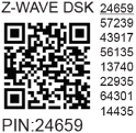
The first five digits of the key are highlighted or underlined to help the user identify the PIN Code part of the DSK text. The DSK is additionally represented with a QR Code as shown on the image.
DSK label and QR code (example)
A joining node requesting to join the S2 Access Control Class or the S2 Authenticated Class will obfuscate its Public Key by setting the bytes 1..2 to zeros (0x00) before transferring its key via RF.
The DSK may be used for out-of-band (OOB) authentication.
Z-Wave® Parameters
Click here to see the Z-Wave Parameters
Parameter No. 1 - SW (SW1) Switch type
This parameter defines how the Device should treat the switch (which type) connected to the SW (SW1) terminal.
Value size: 1 Byte
Default value: 2
Values & descriptions:
-
0 - momentary switch,
-
1 - toggle switch (contact closed - ON / contact opened - OFF),
-
2 - toggle switch (device changes status when switch changes status)
Parameter No. 17 - Restore state of O (O1) after power failure
This parameter determines if the on/off status is saved and restored for the load connected to O (O1) after a power failure.
Values size: 1 Byte
Default value: 0
Values & descriptions:
-
0 - Device saves last on/off status and restores it after a power failure
-
1 - Device does not save on/off status and does not restore it after a power failure, it remains off
Parameter No. 19 - O (O1) Auto OFF with timer
If the load O (O1) is ON, you can schedule it to turn OFF automatically after the period of time defined in this parameter. The timer resets to zero each time the Device receives an ON command, either remotely (from the gateway or associated device) or locally from the switch.
Values size: 2 Byte
Default value: 0
Values & their descriptions:
Parameter No. 20 - O (O1) Auto ON with timer
If the load O (O1) is OFF, you can schedule it to turn ON automatically after the period of time defined in this parameter. The timer resets to zero each time the Device receives an OFF command, either remotely (from the gateway or associated device) or locally from the switch.
Values size: 2 Byte
Default value: 0
Values & their descriptions:
The set value determines the relay contact type for output O (O1). The relay contact type can be normally open (NO) or normally closed (NC).
Values size: 1 Byte
Default value: 0
Values & descriptions:
Relay logic:
| par-NO/NC | command (switch, zwave,..) | Device output state |
| NO (0) | OFF | OFF (0 V) |
| NO (0) | ON | ON (230 V) |
| NC (1) | OFF | ON (230 V) |
| NC (1) | ON | OFF (0 V) |
Parameter No. 25 - Set timer units to s or ms for O (O1)
Set the timer units to seconds or milliseconds. Choose if you want to set the timer in seconds or milliseconds in Parameters No. 19, 20.
Values size: 1 Byte
Default value: 0
Values & descriptions:
Parameter No. 36 - O (O1) Power report on change - percentage
This parameter determines the minimum change in consumed power that will result in sending a new report to the gateway.
Values size: 1 Byte
Default value: 50
Values & descriptions:
NOTE: Regardless of the power consumption change in percentage, the report will not be sent more frequently than defined by Parameter No. 39.
Parameter No. 39 - Minimum time between reports (O) O1
This parameter determines the minimum time that must elapse before a new power report on O (O1) is sent to the gateway.
Values size: 1 Byte
Default value: 30
Values & descriptions:
NOTE: This Parameter is in relation to Parameter No. 36.
NOTE: Setting the value to less than 30s can cause the Z-Wave network congestion state (slow Device response and decreased network stability).
Parameter No. 91 - Water Alarm
This parameter determines which alarm frames the Device should respond to and how. The parameters consist of 4 bytes, the three most significant bytes are set according to the official Z-Wave protocol specification.
Values size: 4 Byte
Default value: 0
Values & descriptions:
-
0 no action
-
1 open relay
-
2 close relay
Parameter No. 92 - Smoke Alarm
This parameter determines which alarm frames the Device should respond to and how. The parameters consist of 4 bytes, the three most significant bytes are set according to the official Z-Wave protocol specification.
Values size: 4 Byte
Default value: 0
Values & descriptions:
-
0 no action
-
1 open relay
-
2 close relay
Parameter No. 93 - CO Alarm
This parameter determines to which alarm frames and how the device should react. The parameters consist of 4 bytes, three most significant bytes are set according to the official Z-Wave protocol specification.
Values size: 4 Byte
Default value: 0
Values & descriptions:
-
0 no action
-
1 open relay
-
2 close relay
Parameter No. 94 - Heat Alarm
This parameter determines which alarm frames the Device should respond to and how. The parameters consist of 4 bytes, the three most significant bytes are set according to the official Z-Wave protocol specification.
Values size: 4 Byte
Default value: 0
Values & descriptions:
-
0 no action
-
1 open relay
-
2 close relay
Parameter No. 120 - Factory Reset
Reset to factory default settings and removed from the Z-Wave network.
The parameter is Advanced and may be hidden under the Advanced tag.
Values size: 1 Byte
Default value: 0
Values & descriptions:
Parameter No. 201 - Serial Number 1
This parameter contains a part of device’s serial number.
The parameter is Read-Only and cannot be changed.
The parameter is Advanced and may be hidden under the Advanced tag.
Values size: 4 Byte
Default value: Device specific
Values & descriptions:
Parameter No. 202 - Serial Number 2
This parameter contains a part of device’s serial number.
The parameter is Read-Only and cannot be changed.
The parameter is Advanced and may be hidden under the Advanced tag.
Values size: 4 Byte
Default value: Device specific
Values & descriptions:
Parameter No. 203 - Serial Number 3
This parameter contains a part of device’s serial number.
The parameter is Read-Only and cannot be changed.
The parameter is Advanced and may be hidden under the Advanced tag.
Values size: 4 Byte
Default value: Device specific
Values & descriptions:
Z-Wave® Command Classes
Click to see the Z-Wave Command Classes
-
ASSOCIATION_V2 [S0, S2]*
-
ASSOCIATION_GRP_INFO_V3 [S0, S2]*
-
BASIC_V2 [S0, S2]*
-
SWITCH_BINARY_V2 [S0, S2]*
-
CONFIGURATION_V4 [S0, S2]*
-
DEVICE_RESET_LOCALLY_V1 [S0, S2]*
-
FIRMWARE_UPDATE_MD_V5 [S0, S2]*
-
INDICATOR_V3 [S0, S2]*
-
MANUFACTURER_SPECIFIC_V2 [S0, S2]*
-
METER_V6 [S0, S2]*
-
MULTI_CHANNEL_ASSOCIATION_V3 [S0, S2]*
-
NOTIFICATION_V8 [S0, S2]*
-
POWERLEVEL_V1 [S0, S2]*
-
SECURITY_V1
-
SECURITY_2_V1
-
SUPERVISION_V1
-
TRANSPORT_SERVICE_V2
-
VERSION_V3 [S0, S2]*
-
ZWAVEPLUS_INFO_V2
[S2]* Security S2 Command Class
Z-Wave® Notifications Command Class
Click to see the Z-Wave Notification Command Class
Overheat detected
| Comment | Overheat detected |
| Z-Wave Notification Type Name | Heat Alarm |
| Z-Wave Notification type - Value | 0x04 |
| Z-Wave Notification type - Event | State |
| Z-Wave Notification Name | Overheat detected |
| Z-wave Notification Name - Value | 0x02 |
| Z-Wave Notification Name - Version | V2 |
| Z-Wave Device specific | Yes |
| LED signalisation | Check LED signalisation table |
| Device reaction - Switch OFF all outputs and send notification | Yes |
| Action to restore - power cycle | Yes |
| Action to restore - short press on S button | Yes |
| Action to restore - press any switch-push button connected to any SW (SW, SW1, SW2, …) terminal | Yes |
Over-current detected O
| Comment | Over-current detected O (O1) |
| Z-Wave Notification Type Name | Power management |
| Z-Wave Notification type - Value | 0x08 |
| Z-Wave Notification type - Event | State |
| Z-Wave Notification Name | Over-current detected |
| Z-Wave Notification Name - Value | 0x06 |
| Z-Wave Notification Name - Version | V3 |
| LED signalisation | Check LED signalisation table |
| Device reaction - Switch OFF the output O (O1) and send a notification | Yes |
| Action to restore - power cycle | Yes |
| Action to restore - short press on S button | Yes |
| Action to restore - press any switch-push button connected to any SW (SW, SW1, SW2, …) terminal | Yes |
AC mains disconnected
| Comment | AC mains disconnected (valid for AC and DC power supply) |
| Z-Wave Notification Type Name | Power management |
| Z-Wave Notification type - Value | 0x08 |
| Z-Wave Notification type - Event | State |
| Z-Wave Notification Name | AC mains disconnected |
| Z-Wave Notification Name - Value | 0x02 |
| Z-Wave Notification Name - Version | V2 |
| LED signalisation | Check LED signalisation table |
| Device reaction - Switch OFF all outputs and send notification | Yes |
| Action to restore - power cycle | Yes |
| Action to restore - short press on S button | Yes |
| Action to restore - press any switch-push button connected to any SW (SW, SW1, SW2, …) terminal | Yes |
Over-voltage detected
| Comment | Over-voltage detected |
| Z-Wave Notification Type Name | Power management |
| Z-Wave Notification type - Value | 0x08 |
| Z-Wave Notification type - Event | State |
| Z-Wave Notification Name | Over-voltage detected |
| Z-Wave Notification Name - Value | 0x07 |
| Z-Wave Notification Name - Version | V3 |
| LED signalisation | Check LED signalisation table |
| Device reaction - Switch OFF all outputs and send notification | Yes |
| Action to restore - power cycle | Yes |
| Action to restore - short press on S button | Yes |
| Action to restore - press any switch-push button connected to any SW (SW, SW1, SW2, …) terminal | Yes |
Z-Wave® Associations
Click to see the Z-Wave Associations
Associations are used for direct communication between the Device and other devices within your Z-Wave network without the need of the Z-Wave gateway.
Max. number of associated devices per group is 9. This value is fixed and cannot be configured.
Each association group supports the association of up to 9 devices (nodes). To avoid network delays, we recommend limiting the number of associated devices to no more than 5 per group. "Lifeline group" is reserved for controlling devices, such as Gateways and remote controllers, or devices who can interpret the reports sent.
Association group 1 – "Lifeline group" sends to the controlling device it's command class notifications and or command class reports when said command classes are triggered. Max. 9 nodes are allowed:
Root device
Root Device - Association group 1 – Lifeline
-
INDICATOR_REPORT : LED status
-
DEVICE_RESET_LOCALLY_NOTIFICATION : triggered upon request
-
SWITCH_BINARY_REPORT : status change report for output O (O1)
-
NOTIFICATION_REPORT : triggered on Overheat
-
NOTIFICATION_REPORT : triggered on Over-current detected O (O1)
-
NOTIFICATION_REPORT : triggered on Over-voltage detected
-
NOTIFICATION_REPORT : triggered on AC mains disconnected
-
METER_REPORT : triggered by load power consumption connected to output O(O1) (according to the settings of Parameters No. 36 and 39)
Association Group 2
Allowed nodes: 9
It is assigned to switch connected to the SW (SW1) terminal (uses Basic command class).
Triggered by SW (SW1). The device sends according to the state of SW (SW1) (switch or push-button) the command BASIC_SET ON or BASIC_SET OFF to the associated device. This command is reflected to the output of associated device. Supports the following command classes:
Association Group 3
Allowed nodes: 9
It is assigned to switch connected to the SW (SW1) terminal (uses Switch Multilevel command class). Triggered by SW (SW1).
It is recommended to use push buttons for this association. Supports the following command classes:
-
SWITCH_MULTILEVEL_START_LEVEL_CHANGE : initiate a transition to a new level (increase or decrease light intensity in case of dimmer, or move shutter up or down, …)
-
SWITCH_MULTILEVEL_STOP_LEVEL_CHANGE : stop an ongoing transition (stop increase or decrease light intensity in case of dimmer, or stop moving shutter up or down, …)
Z-Wave® Important disclaimer
Z-Wave® wireless communication may not always be 100% reliable. This Device should not be used in situations in which life and/or valuables are solely dependent on its functioning. If the Device is not recognized by your gateway or appears incorrectly, you may need to change the Device type manually and ensure that your gateway supports Z-Wave Plus™ multi-level devices.
Troubleshooting
For troubleshooting please visit our support portal: Support
Compatibility
| Wave 1 mini | functions - reports |
| Gateway | On/Off | SW On/Off | Notes |
| Home Assistant | | | |
| Fibaro HC 3 / Z-Wave engine 3 | | | |
| Homey | | | |
| Homee Cube Gen 7 | | | |
| Homee Cube Gen 5 | | ❌ | |
| Smart Things | | | with the Shelly Wave edge driver |
| Vera Ezlo | | | |
| Cozify | | | |
| Legend |
| Symbol | State |
| | Working / Possible |
| ❌ | Not Working / Not Possible |
| P | Partially |
| N/T | Not Tested |
| TBD | To be done |
| Function | Meaning / tested |
| On/Off | if device respond to the app UI On/Off command |
| SW On/Off | if device reports On/Off changes by SW input |
| Dimming | if device respond to app UI dimming command |
| SW Dimming | if device report dimming state change by SW input |
| Watts | if Watts are reported (unsolicited) |
| kWh | if kWh are reported (unsolicited) |
| Up/Down | if device respond to the app UI Up/Down command |
| SW Up/Down | if device reports Up/Down changes by SW input |
| Slats | if the slats respond to the app UI command |
| SW Slats | if the slats report the changes done by SW |
| D control | detached mode if device reports scene commands single press, double press,… |
| D Binary | detached mode if the device reports binary On/Off by SW input |
| Sensor # | Is the sensor report visualized in the gateway, type of sensor in the notes. |
Gateway guides
You may find useful guides on gateways in the Z-Wave Shelly Knowledge base.
Compliance
Printed User Guide
Wave_1PM_mini_user_guide_multilang_V3.pdf